Mech-Eye Industrial 3D Camera cabling guide
The cabling of the Mech-Eye Industrial 3D Camera (“camera”) mainly includes two parts: camera power and network connection. This article mainly introduces the cabling methods of the camera, precautions, specifications for camera inputs and outputs, and cabling diagrams for power and network interfaces.
Camera power cabling and precautions
Mech-Mind mainly provides two power supply schemes: 24V DC power supply and usage of adapter, for details, please refer to Component list: structured light camera cables. It is recommended to use the 24V DC power supply scheme in industrial environments.
Camera power cabling method
As shown in the figure below, insert the aviation plug of the DC power cord into the DC 24V power interface of the camera. For detailed information, please refer to Hardware User Manual - Connect the Camera.


-
Align the bump in the connector with the notch in the port.
-
Tighten the nut. The recommended tightening torque is 0.7 N·m. A gap of about 2 mm remains after the nut is fully tightened.
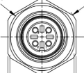
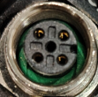
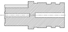
The difference between the physical power connector and the drawing:
There is a discrepancy between the physical M12 power connector and drawing. On the physical connector, there is an additional non-functional blind via in the middle, while the drawing only shows vias for power conducting without indicating this blind via. This blind via does not alter the electrical characteristics of the connector and does not affect its connection and use with the corresponding socket.
| Drawing | Physical connector | Cross section of the connector |
|---|---|---|
 |
 |
 |
DIN rail power switch connection
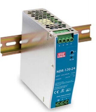
This section describes the DIN rail power supplied by Mech-Mind. If using a different model, please follow the corresponding manual for correct connection.
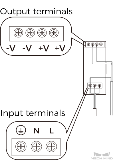
The AC power line has three prongs: L, N, PE (![]() ). When connecting, ensure they match the input terminals correctly.
). When connecting, ensure they match the input terminals correctly.
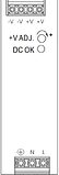
The DC power line has three prongs: +V, -V, PE (![]() ). When connecting, ensure correct matching of positive and negative voltages, following the principle of one positive and one negative, to ensure correct polarity of the power line.
). When connecting, ensure correct matching of positive and negative voltages, following the principle of one positive and one negative, to ensure correct polarity of the power line.
Cabling precautions
Precautions for using adapters
- Connect the power last. After the power is connected, the PWR indicator light should remain green. If not, contact Mech-Mind team immediately.
- Grounding is already completed through the three-phase power line, so no additional grounding is necessary.
- When connecting the camera power interface, ensure stability and leave some redundancy.
- For related cabling schemes, please refer to Guidelines for mounting camera cables.
Precautions for using DIN rail power
- Connect the power last. After connecting the power, ensure the PWR indicator light remains green. If any abnormality occurs, contact Mech-Mind team.
- DIN rail power must be used within the distribution box.
- When connecting the DC cable of the rail power, follow the labels on the cable. Note that the wire colors may vary between different batches.
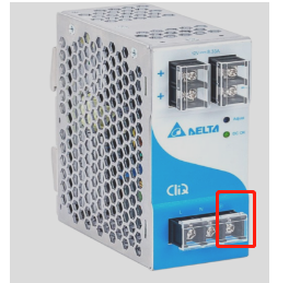
- AC L, N, PE must be connected to the three terminals of the rail power, ensuring effective grounding (see the red box in the lower left image below).
- For related cabling schemes, please refer to Guidelines for mounting camera cables.
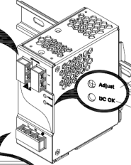
- Attention: Cables over 20 meters require a 2V boost (see the voltage adjustment in the lower right image below).
Voltage adjustment method: According to the diagram below, rotate ADJ clockwise to increase the output voltage and use a multimeter to measure the voltage between -V and +V. Adjust the output voltage until it reaches 26V.
Camera power input and output requirements
| NDR-120-24(preferred) | DRL-24V120W1EN | |||
|---|---|---|---|---|
| Power Input | Input Ratings / Characteristics | ||||
| Voltage range | Nominal input voltage | 100~240VAC | 90 ~ 264VAC | 100~240VAC | |
| Frequency range | Nominal input frequency | 47 ~ 63Hz | 47 ~ 63Hz | 47 ~ 63Hz | |
| AC current | Input current | > 2A / 100VAC, 0.8A / 240VAC | 2.25A/115VAC 1.3A/230VAC | 2.1A/115VAC 1.3A/230VAC | |
| Surge current | Max inrush current | < Startup: 60 A/ 100AC, 120A / 240VAC | 20A/115VAC 35A/230VAC | 35A/230VAC | |
| Leakage current | Leakage current | < 1mA / 240VAC | <1mA / 240VAC | <0.5mA / 240VAC | |
| Overvoltage | Overvoltage | Rated output voltage 105% to 135%. Protection mode: cutoff output voltage, restart to recovery | 29 ~ 33V | <17.4V, SELV output, lock mode <33.6V, SELV output, lock mode <64.8V, SELV output, lock mode | |
| Power output | Output ratings / Characteristics | ||||
| DC voltage | Nominal output voltage | 24V ±1V | 24V | 24 Vdc | |
| Rated current | Output current | >3.75A | 5A | 5.0 A | |
| Rated power | Output power | >90W | 120W | 120 W | |
| EMC | ||||
| Conducted emission | Class B | Class B | Class B | |
| Radiated emission | Class B | Class B | Class B | |
| Harmonic current | Class A | Class A | Class A | |
| Voltage flicker | Pass | Pass | Pass | |
| ESD | Level 4, 15KV air; Level 4, 8KV contact | Level 4, 15KV air; Level 4, 8KV contact | Level 4, 15KV air; Level 4, 8KV contact | |
| RF field susceptibility | Level 2, 3V/m | Level 2, 3V/m | Level 2, 3V/m | |
| EFT bursts | Level 3, 2KV/5KHZ/100KHZ | Level 3, 2KV/5KHZ/100KHZ | Level 3, 2KV/5KHZ/100KHZ | |
| Surge susceptibility | Level 3, 1KV/Line-Line , 2KV/Line-FG | Level 3, 1KV/Line-Line , 2KV/Line-FG | Level 3, 1KV/Line-Line , 2KV/Line-FG | |
| Conducted susceptibility | Level 3, 10V/m | Level 3, 10V/m | Level 3, 10V/m | |
| Magnetic field immunity | Level 2, 3A/m | Level 2, 3A/m | Level 2, 3A/m | |
| Voltage dips, interruption | >95% dip 0.5 periods, 30% dip 25 periods, >95% interruptions 250 periods | >95% dip 0.5 periods, 30% dip 25 periods, >95% interruptions 250 periods | >95% dip 0.5 periods, 30% dip 25 periods, >95% interruptions 250 periods |
Power interface cabling diagram
The power supply interface for Mech-Eye industrial 3D cameras is an M12 4PIN A-coded aviation plug. For specific details, please refer to the DC Power Cable Datasheet in the Component list: structured light camera cables.
- Pay attention to the orientation when inserting the aviation plug connector, and it is recommended to secure the cables after cabling.
- It is recommended to use a 24V isolated adapter or a 24V isolated rail power supply for power supply.
- When using longer power cables, ensure that the voltage at the output end is 24V.
Camera network cabling and precautions
Camera network cabling method
As shown in the diagram below, insert the aviation plug of the Ethernet cable into the ETH port of the camera, and insert the RJ45 connector into the port of the IPC. When connecting the camera to the IPC, it is recommended to use a switch for connection. For detailed information, please refer to Hardware User Manual - Connect the Camera.

Precautions for using industrial switches and routers
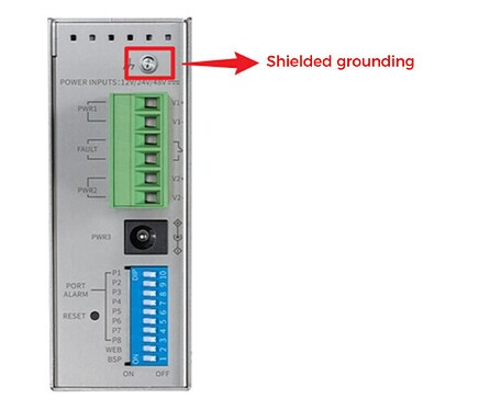
- It is best to use industrial-grade switches and routers with grounding terminals and ensure good grounding.
- The grounding wire of the switch should be made of internal copper wire with a diameter of at least 4 square millimeters and colored yellow-green.
- If the robot’s network cable is also connected to the switch/router, avoid grounding the shielding layer of the robot’s network cable.
For example: Industrial switches with grounding terminals, such as TP-LINK TL-SG2008.
Precautions for connecting camera network cable to IPC
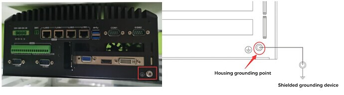
Note: In the right image above, the red circle on the left is a housing grounding point, and on the right is a shielded grounding device.
Network interface cabling diagram
The network interface for Mech-Eye industrial 3D cameras is an M12 8PIN A-Coded aviation plug. For detailed information, please refer to the Ethernet Cable Datasheet in the Component list: structured light camera cables.