Problem
Every time I captured an image and ran the Mech-Vision project, there were always deviations in the calculated poses of some parts.
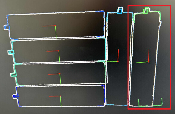
As shown in the image below, the detected pose of the workpiece in the red box deviates from the center.
Setup & context
- Software version: Mech-Vision, Mech-Viz, and Mech-Center of version 1.7.0
- Camera model: Laser L v3 camera
- Working distance: The workpieces at the bottom are about 2800 mm away from the camera
- The quality of the workpiece point clouds is good.
- The workpieces are castings and the difference between their sizes is small.
When there was an occasional deviation, it was found that there was an error in the 3D matching Step.
We cannot find the reason why there is always a picking deviation for the current case. Can anyone help us with it?
The on-site video is attached below. If the vacuum gripper fails to grip the workpiece at the optimal spot for picking, the workpiece may be dropped.
Possible reasons for deviations in pose calculation:
- An error occurred in the calculation of 3D matching Steps in the Mech-Vision vision processing project. The Step parameters should be adjusted.
- There is a deviation of the camera’s extrinsic parameters. Please check the camera’s extrinsic parameters.
If a picking deviation occurred, the possibility of robot error still cannot be ruled out. Please check whether the accuracy of the robot and the accuracy of its tool center point meet the requirement.
Adjust parameters in 3D matching Steps
-
First, set the “Deviation Correction Capacity” in Step “3D Fine Matching Lite” to “Large” and see whether the matching result can be improved.
-
If adjusting this parameter itself cannot fix the problem, please adjust other matching parameters according to the results from coarse matching and fine matching.
Parameter tuning instructions for 3D matching Steps:
Check whether the camera extrinsic parameters are correct. If not, please re-calibrate.
A quick way to verify camera extrinsic parameters:
- Step 1: Move the robot manually to a position under the camera, capture an image of the robot, and sends the robot point cloud to Mech-Viz.
- Step 2: Connect the robot via Mech-Center, and synchronize the robot in Mech-Viz. If the simulated robot coincides with the robot point cloud sent by Mech-Vision in Mech-Viz’s 3D simulation area, the accuracy of extrinsic parameters meets the requirement.
Please see User Manual “Error Control” for the general ideas of error control and troubleshooting.
