For the latest information, see the documentation.
Optimize the camera’s parameters
1. Parameters of depth maps and point clouds
1.1 Main influencing parameters
3D “Exposure Time”
Do not set a long 3D “Exposure Time”. Increase “Gain” instead if necessary.
“Exposure Multiplier”
The capturing time is the shortest when this parameter is set to 1. It should not be increased beyond necessity.
“Fringe Coding Mode”
The capturing time is shorter when this parameter is set to “Fast”. If it is set to “Accurate”, more fringe pattern images will be involved for generating depth maps and capturing will be slow.
1.2 Secondary influencing parameters
“ROI”
Set the ROI properly and the calculation time will be shorter. This parameter has little influence on imaging but better adjust it depending on specific circumstances.
“Point Cloud Processing”
Unable this function and the calculation time will be shorter. Parameters in this function have little influence on imaging but better adjust them depending on specific circumstances.
1.3 Parameters of specific camera models
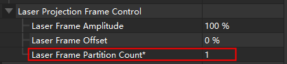
“Laser Frame Partition Count”
This parameter multiplies capturing time.
The setup method is as shown in the following image. While in Administrator mode, set “Visibility” to Expert to adjust “Laser Frame Partition Count”.
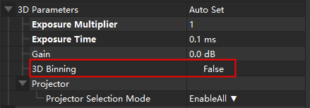
“3D Binning”
For DEEP, Laser L Enhanced-12MP, and Pro L Enhanced-12MP cameras, select the Enable Binning checkbox to reduce the imaging time.
The setup method is as shown in the following image. While in Administrator mode, set “Visibility” to Expert to adjust “3D Binning”.
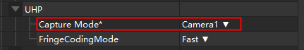
UHP “Capture Mode”
“Merge” mode takes time in merging images, so setting this parameter to “Camera1” or “Camera2” reduces the imaging time.
The setup method is as shown in the following image:
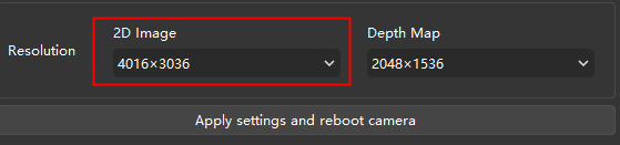
2. Parameters of 2D images
2.1 Main influencing parameters
2D “Exposure Time”
When “Exposure Mode” is set to “Timed”, better not set a long 2D “Exposure Time”.
2D “Exposure Mode”
- “Flash”: This mode amounts to when “Exposure Multiplier” is set to 0. And the fringe pattern images for generating depth maps when the projector is on will be used.
- “Timed”: This mode amounts to when “Exposure Multiplier” is set to 1. And exposure time will be fixed.
- “Auto”: This mode amounts to when “Exposure Multiplier” is set to more than 1. And imaging time will be longer.
Basically: imaging time (“Flash” mode) < imaging time (“Timed” mode) < the imaging time (“Auto” mode).
2.2 Parameters of specific camera models
“2D Binning”
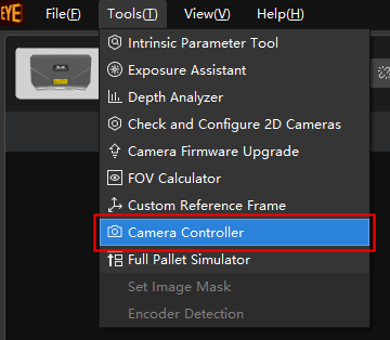
For LSR L and LSR S cameras, adjust the “2D Binning” to reduce the imaging time.
The setup method is as depicted in the images below: Start by entering the Administrator mode, then open the “Camera Controller” from the “Tools” section in the menu bar. This will allow you to configure “2D Binning”.
Improve the camera’s Internet connection
Check Internet speed in Mech-Eye Viewer.
It should be faster than 700 Mbps, meaning standard Gigabit Ethernet (GbE). For NANO and PRO XS cameras, when the Internet speed displayed is between 300 to 500 Mbps, the Internet connection is fine.

If the Internet speed is slower than a standard GbE
- IPC network interface card (NIC): Disable unnecessary NICs. Change a network port. Divide a network into multiple segments that act as independent networks. Check if the IPC’s NIC driver and the IPC’s settings require upgrades, for example, the upgrade about removing the Internet speed limit.
- GbE: Switches, routers, and network cables must ensure support for gigabit networks.
- Network cable connection: Check the camera and the IPC’s network cable connection to make sure that all cables are connected normally.
- Cable status: Inspect for cable bends or damages and replace the camera network cables when needed.