Solution Scenario
In most bin-picking projects, after the gripper picks a workpiece from the bin, there may be abnormal situations in addition to normal successful picking, such as empty picking, reversed picking, double picking, large picking pose deviation, or picking errors exceeding the accuracy requirements of the downstream placement process.
Therefore, a 3D camera can be used for initial recognition and picking localization inside the bin. After the workpiece is picked out of the bin, a 2D camera can be used for picking status detection and secondary recognition . This makes it possible to determine whether the workpiece has been correctly picked, while also compensating and correcting the actual pose after picking, thereby further improving final placement accuracy and overall system stability.
This document uses the new 2D smart camera to perform secondary recognition and positioning for long slender rod-like workpieces after they are picked out of the bin. The solution focuses on compensating the axial position error of the workpiece and updating the placement position in real time in the UR robot system , thereby improving final placement accuracy and system stability.
Solution Advantage
● Seamless Compatibility with Existing Lastest System
The Mech-Mind 2D smart camera is seamlessly compatible with Mech-Vision 2.2. The algorithm is mature and stable, the configuration is simple, and the system can be quickly integrated.
● Minimal Impact on Overall Cycle Time
The 2D camera uses a capture-on-the-fly method for secondary recognition after picking. The additional cycle time is less than 0.2 s, which has very little impact on the existing bin-picking process.
● Low Cost and Fast Deployment
The 2D camera is low-cost and easy to install and deploy. In this solution, only a fixed-mounted 2D camera is required. No complex calibration is needed to achieve post-picking status detection and placement position compensation.
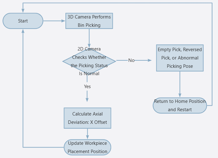
Overall Workflow
Version Information
- Robot: UR5e, 5.12.4.1101661
- 3D Camera: Pros1000M
- 2D Camera: AIC-Lite-050C-08A-W
- Mech-Vision: 2.2.0-a1-dev-03-27
- Gripper: OnRobot 2FG14
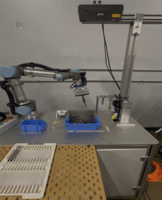
Hardware Setup
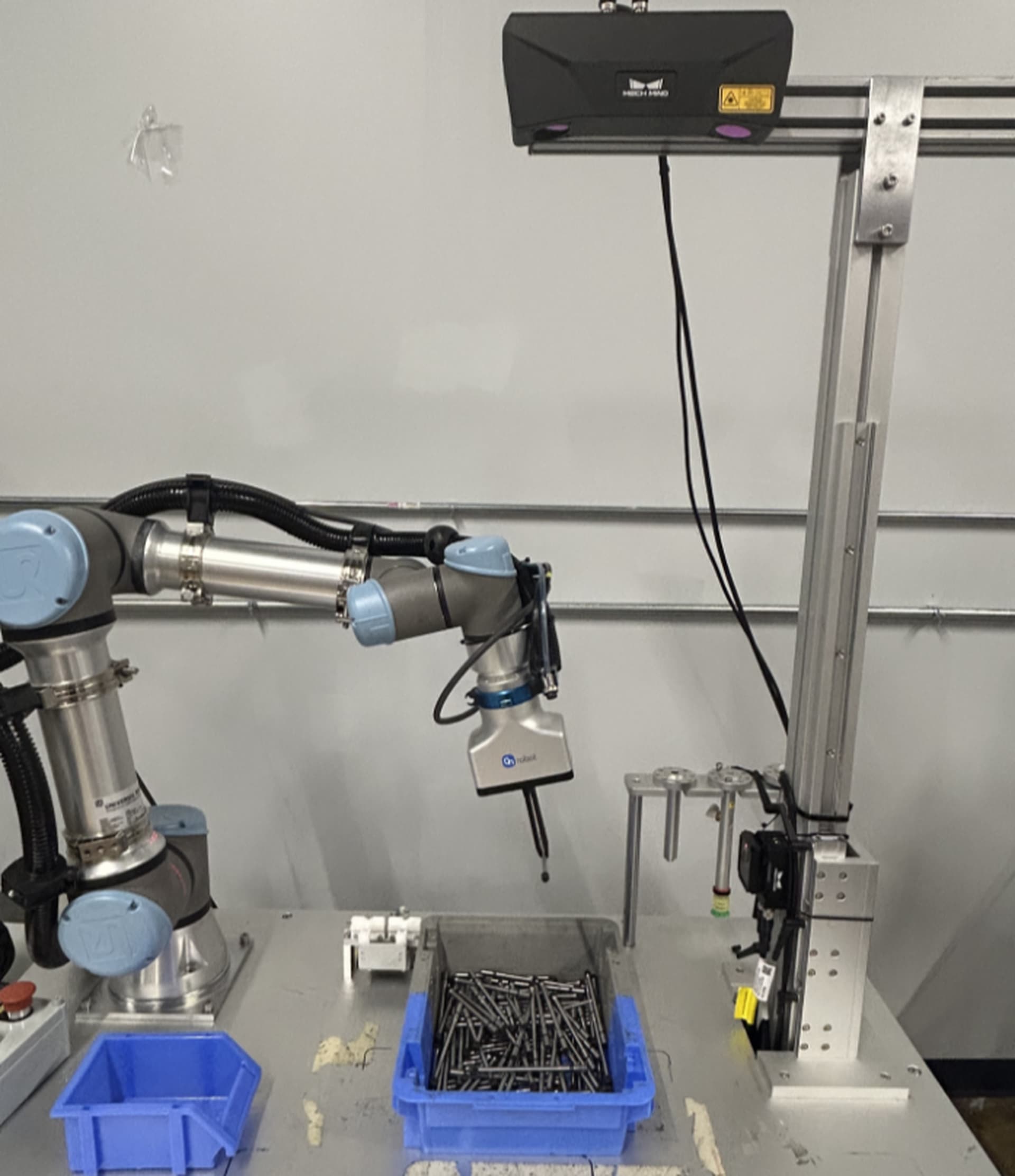
1. Install and Connect the 2D Camera
If the project has high requirements for cycle time, it is recommended to install the 2D camera on the original motion path from the bin-picking position to the placement position. In this way, the robot can complete the capture-on-the-fly inspection during normal transfer, minimizing the impact of 2D camera inspection on the overall cycle time.
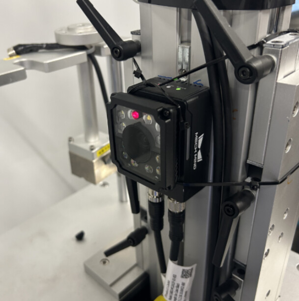
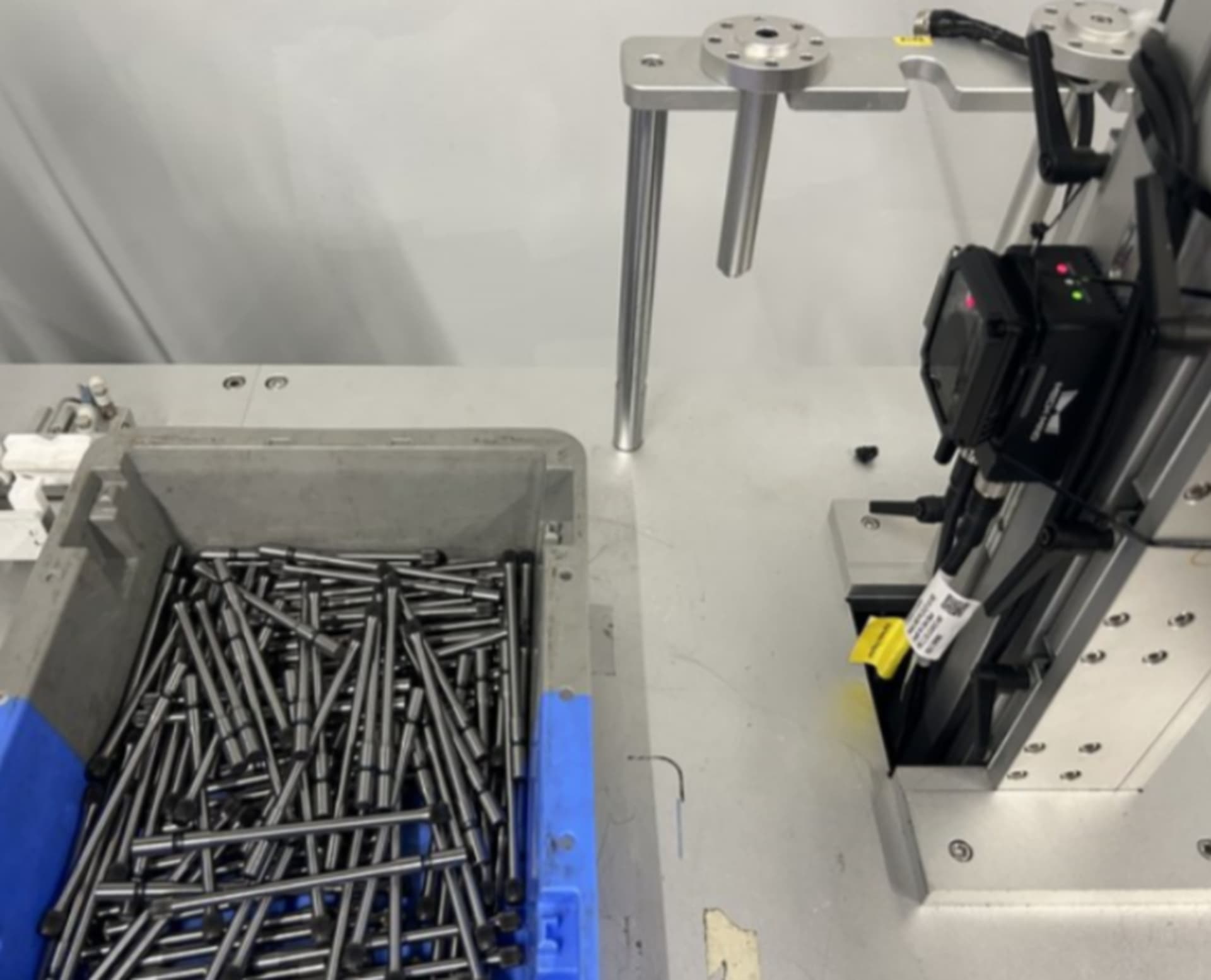
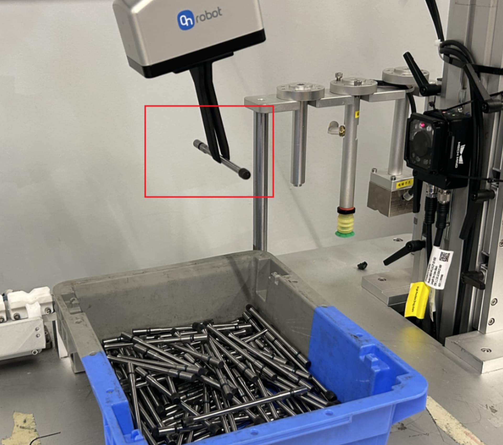
2. Set the 2D Camera Capture Position
First, the robot uses 3D vision to recognize and pick a normal workpiece. Then, the robot moves to the 2D camera inspection area. Adjust the robot pose and 2D camera parameters so that the workpiece is stably displayed in the center of the camera field of view.
After confirming the capture position, this position needs to be recorded on both the robot side and the vision side . During the subsequent model creation process, the workpiece should remain fixed at this position to avoid affecting the model accuracy due to position changes.
As shown below:
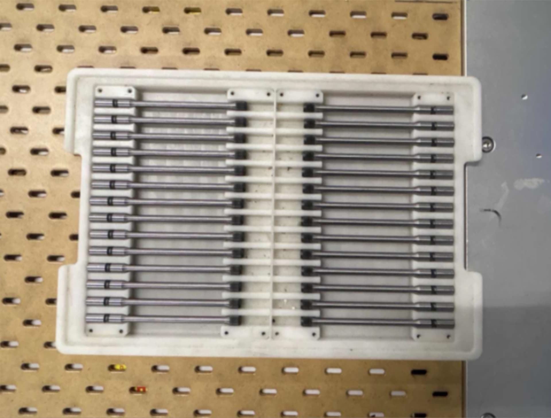
3. Placement Position
The placement position is a tray. The robot needs to place the workpieces into the tray one by one according to the predefined placement order until all placement positions are filled.
Key Steps
Vision Side
The core idea of this solution is:
Use the 2D camera to capture an image so that the workpiece and the background form a clear contrast in the image. This allows the workpiece edge to be extracted stably. Then, the extracted 2D edge is converted into point cloud data for subsequent position calculation and compensation.
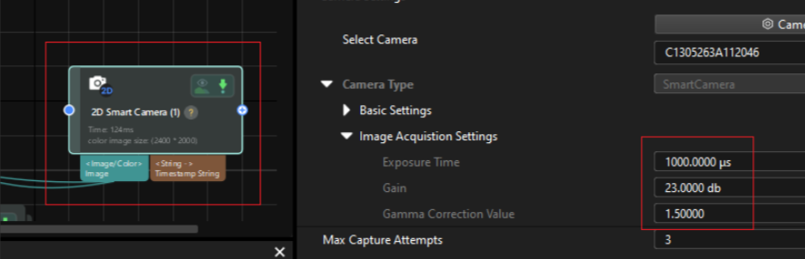
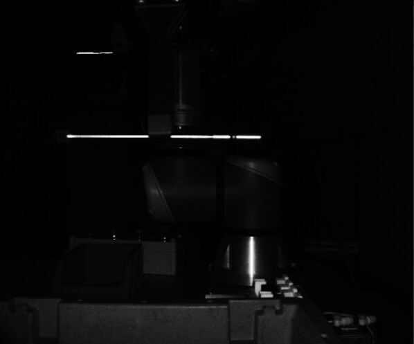
a. Capture the Workpiece
Because the workpiece surface has certain reflective characteristics, after triggering image capture and lighting, obvious bright areas will appear on the workpiece surface, creating a grayscale difference from the background. Based on this difference, the workpiece edge can be extracted more stably.
During debugging, the exposure parameters that can stably distinguish the workpiece from the background should be recorded. The same parameters should then be used in the subsequent 2D Smart Camera step to ensure consistent imaging results.
b. Recognize the Workpiece
In Mech-Vision, use the following steps to convert the 2D edge of the workpiece into point cloud data with normal information.
( Please note that this point cloud is converted from the 2D image edge. Therefore, it is mainly used to describe the position and orientation of the workpiece in the image plane and does not contain real height information in the Z direction. )
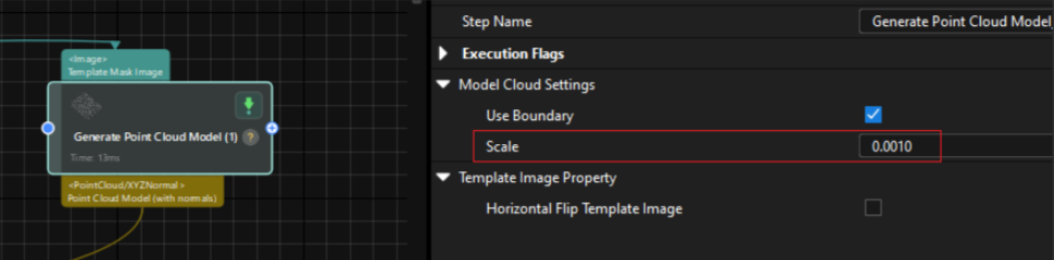
Note: The Scale Factor Must Be Recalculated According to the Actual Application
Since the distance between the workpiece and the 2D camera may vary, the relationship between the 2D image resolution and the actual physical dimensions will also change. Therefore, in actual projects, the corresponding Scale parameter needs to be recalculated according to the workpiece installation height and capture distance.
The recommended calculation method is:
Compare the offset calculated by the vision system with the actual physical offset of the workpiece. Then, recalculate the scale factor based on the difference between the two values. This ensures that the vision calculation result can accurately correspond to the actual compensation value used by the robot.
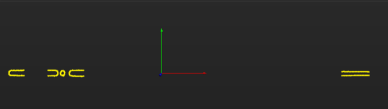
c. Create the Template
Use Import Processed Point Cloud to create the 3Dmatching model.
When creating the 3Dmodel, priority should be given to stable, clear, and repeatable feature areas on the workpiece. This helps improve the stability and positioning accuracy of subsequent 3Dmatching.
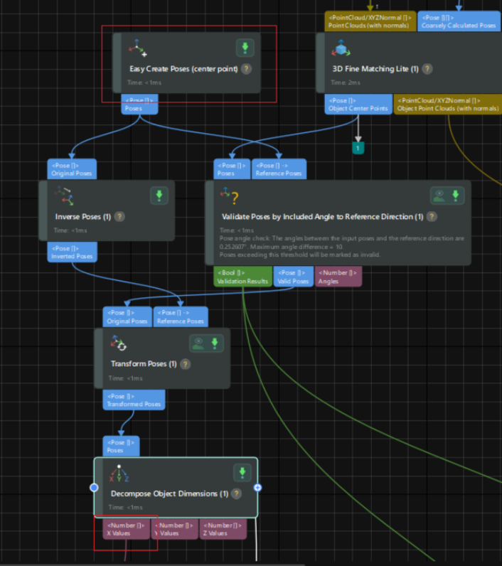
d. Calculate the Axial Deviation: X Offset
Perform matching and localization on the current recognition result. Use the center point of the model created in the previous step as the reference zero position, and calculate the position deviation of the workpiece along the axial X direction .
Explanation :
The vision system can not only calculate the axial position deviation of the workpiece through 3Dmatching, but also determine abnormal picking states based on the matching result.
For example, empty picking, reversed picking, double picking, or abnormal workpiece posture can be filtered by conditions such as matching score and angle deviation. This prevents abnormal workpieces from entering the subsequent placement process.
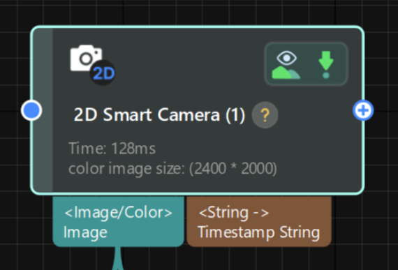
e. Vision Project Cycle Time
The single image capture time of the 2D camera is approximately 0.1 s.
The overall running time of the Mech-Vision project is approximately 0.2 s.
![]()
Robot Side
Robot-Side Position Compensation Logic
After the robot receives the X Offset calculated by the vision system, it updates the tray coordinate system in real time. As a result, all placement positions inside the tray are updated synchronously.
Please note that different robot brands or models may use different methods for coordinate system updating and placement position compensation. The following steps are only for reference based on the current UR robot system.
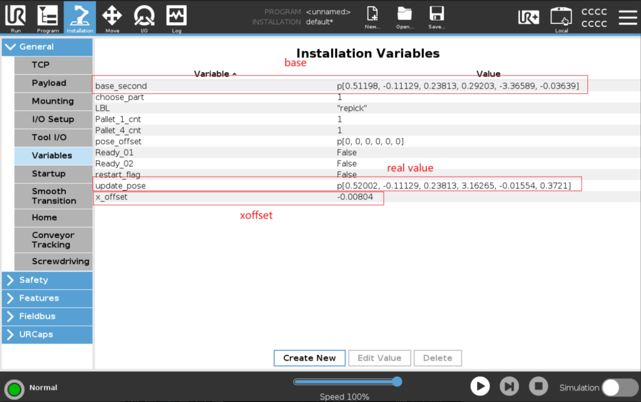
a. Create Related Variables
Create variables in the UR robot program to receive the vision deviation value, record the reference coordinate system, and update the tray coordinate system. These variables prepare the program for subsequent placement position compensation.
Create variables such as:
base_second: reference pose whenx_offset = 0update_pose: real-time updated posex_offset: calculated offset value
Path: Installtion → General → Variables
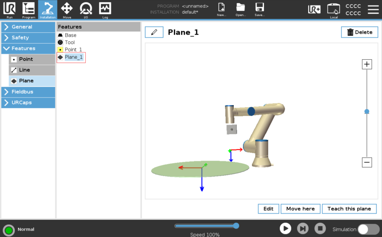
Set the Tray Reference Coordinate System;
Path: Installtion → Features → Plane
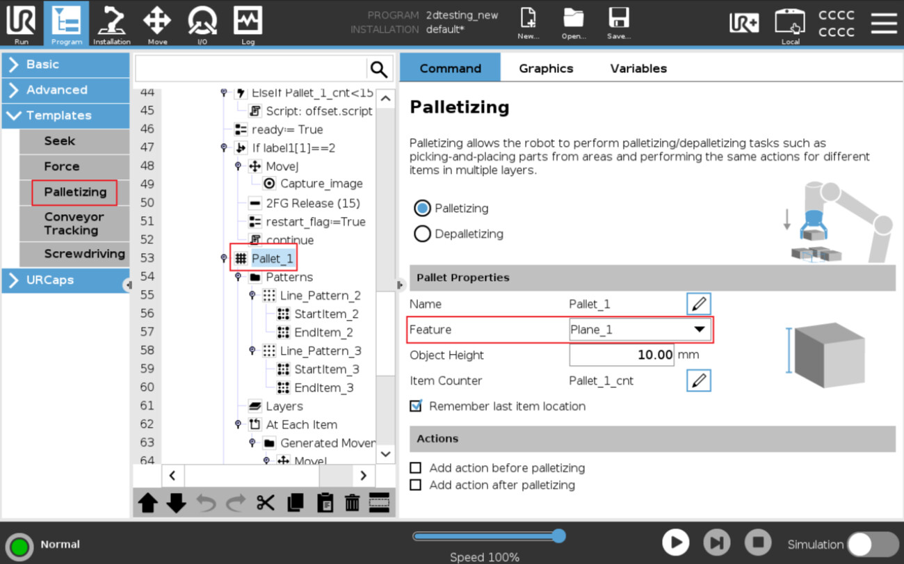
b. Set the Tray Placement Array
The UR robot can use the Palletizing function to create an array placement pattern inside the tray.
When setting it up, pay attention that the Feature used in Palletizing should be the corresponding Plane created and updated in the previous step, instead of the default Base coordinate system.
In this way, after the robot receives the X Offset sent by the vision system and updates this Plane in real time, all array placement points created based on this Plane will be updated synchronously. This realizes overall compensation for all placement positions inside the tray.
Path: Program → Templates → Palletizing
c. Create the Script
Use a Script to realize real-time X-axis offset update of the Plane_1 coordinate system, as shown below:
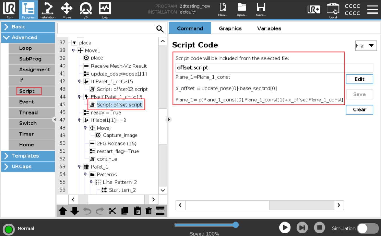
Script Explanation:
#Initialize the tray reference coordinate system
Plane_1 = Plane_1_const

#Calculate the axial X offset
x_offset = update_pose[0] - base_second[0]        #Subtract the first value of base_second from the first value of update_pose


#Update the real-time offset value in the Y direction of Plane_1
Plane_1 = p[
    Plane_1_const[0],
    Plane_1_const[1] + x_offset,      #Update the calculated workpiece offset to the Y direction of the tray coordinate system
    Plane_1_const[2],
    Plane_1_const[3],
    Plane_1_const[4],
    Plane_1_const[5]]
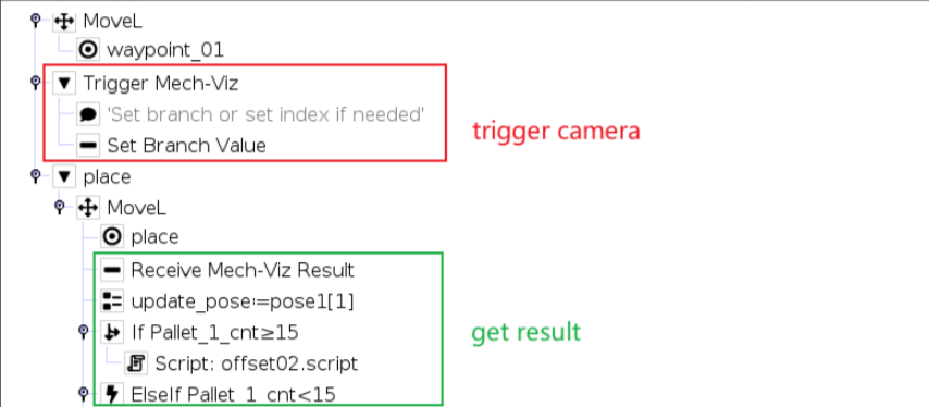
d. Camera Capture-on-the-Fly Program
When the robot reaches the 2D camera capture position, it triggers the camera to take an image. After the capture is triggered, the robot leaves the position in advance without waiting for the entire vision project to finish running.
Before reaching the placement position, the robot can read and check the label result returned by the vision system.
Under normal conditions, the robot receives the X Offset calculated by the vision system, updates the placement position in real time, and then performs the placement action.
Under abnormal conditions, such as empty picking, reversed picking, matching failure, or excessive deviation, the robot can directly return to the Home position or enter another exception-handling process.
The corresponding program is shown below:
Note
If the UR robot triggers Mech-Viz and then immediately triggers Mech-Vision again, it may cause an error on the robot side.
Therefore, in this solution, the 2D camera image capture is also triggered through Mech-Viz . This avoids communication or workflow errors caused by continuously triggering different vision services from the robot side.
Reference Project
The complete reference project and robot program code are as follows:
Mech-Vision:
Vis_project.7z (8.8 MB)
UR Cobot:
2dtesting.7z (7.8 KB)