1. Background
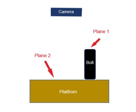
In a Mech-Vision project, if we need to measure the dimensions of an object, we can first obtain point clouds of the two planes and then measure the distance between the point clouds. As illustrated in the diagram below, if we want to know the dimension a of the object, we can first obtain point clouds from Plane 1 and Plane 2, then measure the distance between the point clouds of these two planes.

2. Measurement
2.1 Obtain Point Clouds of Two Planes
To obtain point clouds of the two planes:
-
If two planes are within the same field of view, use the Point Cloud Clustering Step to cluster and separate the point clouds of the two planes. For detailed information on this Step, refer to Point Cloud Clustering.
-
If the two planes are not within the same field of view, use the Transform Point Clouds Step to transform both the two point clouds to the robot reference frame. For detailed information on this Step, refer to Transform Point Clouds.
2.2 Measure the Distance between the Point Clouds
For different ways of camera installation, we have different project designs to measure the distance between the point clouds of the two planes.
2.2.1 Measurement When Camera Horizontally Installed
As shown in the figure below, the camera is horizontally mounted relative to the platform, and there is an object (a bolt) placed on the platform with its height to be measured. We define the upper surface of the bolt as Plane 1 and the upper surface of the platform as Plane 2, and use one of the following two methods to calculate the distance between Plane 1 and Plane 2, which is the height of the bolt.
Method 1: Pose Transformation
Built the Mech-Vision project as instructed in the figure below. On the left side, the Calc Poses and Dimensions from Planar Point Clouds (1) Step obtains the point cloud pose P1 of Plane 1, and on the right side, the Calc Poses and Dimensions from Planar Point Clouds (2) Step obtains the point cloud pose P2 of Plane 2.

The project details:
- Take the X, Y, and Z axes of P2 as the ‘reference point’ frame. Use the Invert Poses Step to invert P2. A matrix of P2 transformed from the camera frame to the object frame (‘reference point’ frame) is obtained.
- Using the Transform Poses Step to multiply P1 by the inverse of P2 to obtain the pose P1’, which is P1 transformed from the camera frame to the ‘reference point’ frame.
- Input P1’ and P2 into the Calc Distance between Two Poses along Specified Direction Step to calculate the distance along the specified axis between the two poses.
Documentations for employed Steps:
- Calc Poses and Dimensions from Planar Point Clouds
- Invert Poses
- Transform Poses
- Calc Distance between Two Poses along Specified Direction
Method 2: Quaternion Replacement
Built the Mech-Vision project as instructed in the figure below. On the left side, the Calc Poses and Dimensions from Planar Point Clouds (1) Step obtains the point cloud pose P1 of Plane 1, and on the right side, the Calc Poses and Dimensions from Planar Point Clouds (2) Step obtains the point cloud pose P2 of Plane 2.

Project details:
- Use the Decompose Poses to Quaternions and Translation Step to decompose the poses of the two planes.
- Assign the quaternions obtained from the decomposition of P2 to P1, and use the Compose Poses from Quaternions and Translation Vectors Step to recombine them into P1’.
- Input P1’ and P2 into the Calc Distance between Two Poses along Specified Direction Step to calculate the distance along the specified axis between the two poses.
Documentations for employed Steps:
- Decompose Poses to Quaternions and Translation
- Compose Poses from Quaternions and Translation Vectors
2.2.2 Measurement When Camera Installed at an Inclined Angle
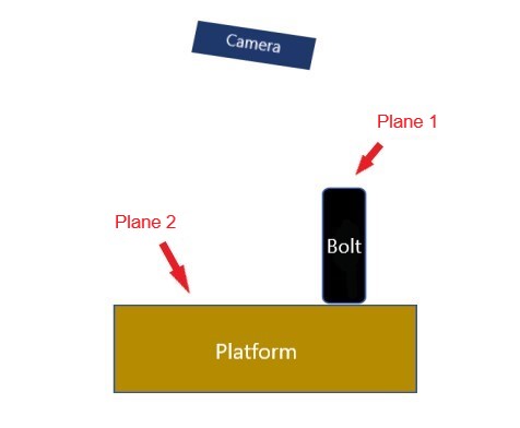
As shown in the figure below, the camera is installed at an inclined angle relative to the platform, and there is an object (a bolt) placed on the platform with its height to be measured. We define the upper surface of the bolt as Plane 1 and the upper surface of the platform as Plane 2, and use one of the following two methods to calculate the distance between Plane 1 and Plane 2, which is the height of the bolt.
Built the Mech-Vision project as instructed in the figure below. On the left side, the Calc Poses and Dimensions from Planar Point Clouds (1) Step obtains the point cloud pose P1 of Plane 1, and on the right side, the Calc Poses and Dimensions from Planar Point Clouds (2) Step obtains the point cloud pose P2 of Plane 2.

Project details:
- Invert P2 to obtain a matrix of P2 that is transformed from the camera frame to the object frame (‘reference point’ frame).
- Using the Transform Poses Step to multiply P1 by the inverse of P2 to obtain the pose P1’, which is P1 transformed from the camera frame to the ‘reference point’ frame.
- Use the Decompose Object Dimensions Step to decompose the dimensions of the bolt in the ‘reference point’ frame, and a height value is obtained. Convert the height value to an absolute value, which is the height of the bolt.
Documentation for employed Step:
Note:
When the camera is installed at an inclined angle, the Calc Distance between Two Poses along Specified Direction Step cannot be used to measure the dimensions of the object. Therefore, the quaternion replacement method cannot be used here as well. The reasons are explained below.
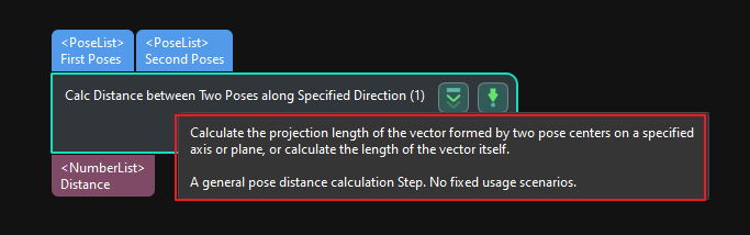

According to the Step function description shown in the above figure, we perform vector operations on two poses to obtain a new pose difference vector, and then project this vector on the Z-axis of the camera frame to obtain the length of the vector on the Z-axis (if, before this step, the pose is transformed from the camera frame to the robot frame, then the projection is performed on the Z-axis of the robot frame).
Due to the inclined installation of the camera, there is an inclination angle between the camera frame and the platform frame. The projection is affected by the inclination angle, resulting in that the measurement result is not the true height of the workpiece. Additionally, changes in the reference point will also affect the result values. Therefore, the Calc Distance between Two Poses along Specified Direction Step cannot be used to measure the dimensions of the object in this scenario.