For the latest information, see the documentation.
Problem
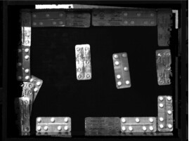
In our case, the multipath effect is most common when reflective bins are involved: light shining on the interior of such bins will reflect on the workpieces in them, therefore affecting stripes of workpieces, leading to defective point clouds.
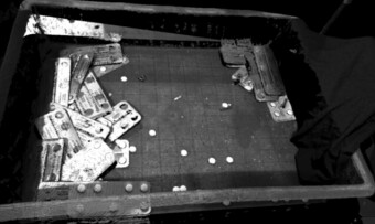
Point cloud screenshots of metal workpieces will be distorted by the multipath effect:
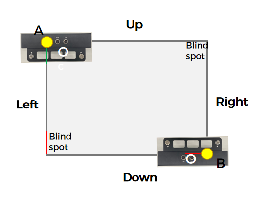
Impact of the bin’s size proportion in the camera’s FOV on the multipath effect

Solid black lines: the light ranges of the projectors (FOV)
Dashed yellow lines: the light projected by the cameras
Solid Red lines: the multipath effect areas
Blue boxes: the bins
| Figure | Proportion of the bin’s size in FOV |
|---|---|
| a | 1/5 |
| b | 1/3 |
| c | 1/2 |
| d | All |
Conclusions:
- The larger the bin occupies the camera’s FOV, the greater the multipath effect on the bin wall. (See the red lines in the figures above)
- When the size of the bin equals to the camera’s FOV, the camera light cannot be projected onto the interior of the bin, thus will not lead to multipath effect on the bin wall.
Solutions
Multipath effect:
- Principle
- Light shining on the interior of reflective bins will reflect on the workpieces in them, therefore affecting the workpieces’ contrast ratio.
- Solutions
- Adjust the camera.
- Adjust the angle between the camera and the workpiece to reduce structured light on the bin’s interior.
- Raise the camera within DOF.
- Move the camera horizontally (see example 1).
- Limit “Laser Frame Amplitude” to reduce structured light on the bin’s interior (disadvantage: for deep bins, only structured light at certain heights will be reduced) (see example 2).
- Adjust the angle between the camera and the workpiece to reduce structured light on the bin’s interior.
- External means.
- Cover the bin’s interior (with dark clothes or low reflective materials) or simply change to a low reflective bin (see example 3).
- Adjust the camera.
Raise the camera
Raise the camera within DOF (see the picture below):
- Smaller the yellow part, less the interference.
- That is to say, higher the camera, less the interference.

Example 1: Move the camera horizontally
Move the camera horizontally to minimize the multipath effect.
Left: The multipath effect is evident on the left side of the bin’s interior.
Right: Both sides of the bin’s interior display a defective point cloud.
Principles of moving horizontally
Move along the Y axis:

Move along the X axis:

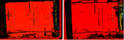
Steps
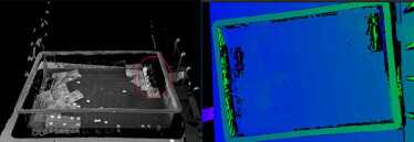
Left: Before adjusting, the left part of the bin’s interior in the screenshot is defective.
Right: After adjusting (move the camera to the left), the left part is no longer defective.
“The two-camera approach”
- Problem: Defective point cloud on both two sides of the bin’s interior.
- Disadvantage of merely moving the single camera (“The one-camera approach”): It only tackles problems on two sides of the moving direction. Problems on other two sides remain unsolved (see principles above).
- Improvement: Adopt “The two-camera approach” to enhance the method of using only one camera.
Front view:

Left view:

Top view:
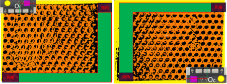
Installation details and a screenshot of point cloud:
Installation details:

Left: The point cloud screenshot of the first camera (top view).
Right: The point cloud screenshot of the second camera (top view).
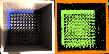
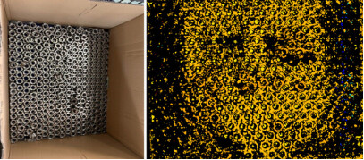
Example 2 (external means): Limit “Laser Frame Amplitude” to reduce structured light on the bin’s interior
Left: Workpieces in a deep bin.
Right: The point cloud screenshot before adjustments.
Solution:
- Set “Laser Frame Amplitude” to 45%, and light reflecting on the interior will be reduced.
- This solution only partially solves the problem, and the limitation of deep bins still remains.

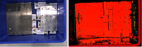
Example 3 (external means): Cover the interior of the bin OR change to a low reflective bin
Cover the interior of the bin:
Use a cloth to cover the bin:
Change to a low reflective bin: