1. In Halcon, the short timeout setting resulted in an extrinsic parameter outcome of 0, 0, 0, 1, 0, 0, 0.
1.1 Issue
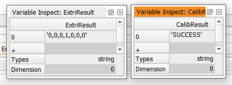
Using the UR10e robot with Euler angle type RPY[°], after collecting 30 poses, the display is as follows:
1.2 Cause
Due to the 30 poses used, the calculation of extrinsic parameters took longer than the initially set timeout of 10 seconds.
1.3 Solution
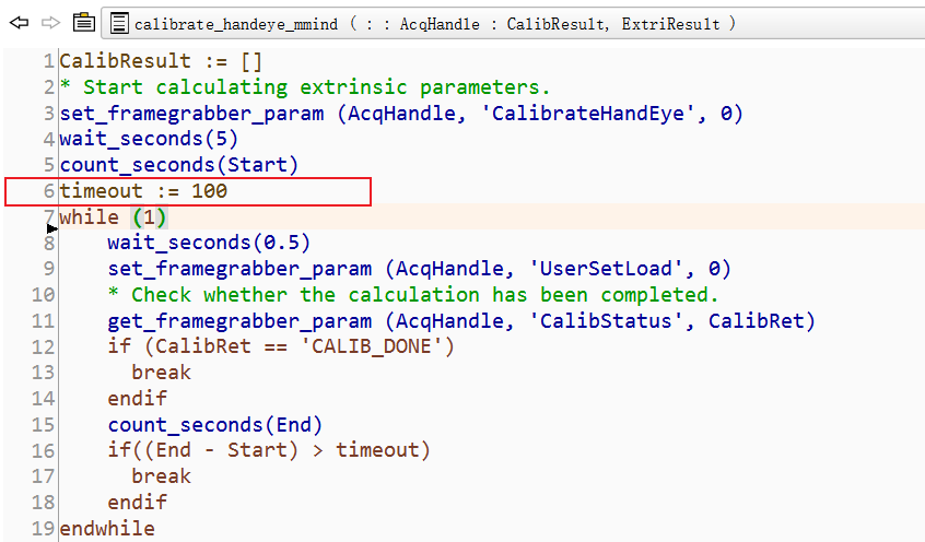
Extend the timeout duration appropriately in the calibrate_haneye_mmind operator, as shown in the following diagram:
2. Irregular poses, subpar robot accuracy, and calibration board movement lead to low extrinsic parameter accuracy.
2.1 Issue
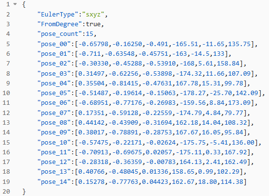
The calibration result from the positioning sample is shown in the following image. It is evident that there is a significant deviation in the X direction. In comparison, the previous calibration method had an error of only 5 mm, whereas the error in the image below is nearly 4 cm.

2.2 Cause
-
The user employed a set of 30 poses with wide coverage and irregular positions, which resulted in poor robustness of the calculation outcomes.
-
Robot accuracy issue: In certain poses, the robot’s accuracy is compromised, leading to the input of erroneous calculation data and consequently introducing deviations in the final results.
-
Rapid robot movement can induce shaking, thereby reducing accuracy.
2.3 Solution
-
The current solution involves calibration based on the provided reference poses and a pyramid rule similar to Mech-Eye Vision: capture more poses to ensure the robot meets the required accuracy standards and maintains stability during movement.
-
Subsequent plans involve incorporating an accuracy verification mechanism for the selected poses and introducing a utility tool for generating poses. These additions aim to assist users in promptly identifying and addressing any accuracy concerns with the robot. To expedite the troubleshooting process, an intermediate data generation mechanism will also be integrated, and calibration accuracy will be displayed upon obtaining the results.
3. Inconsistent units in pose JSON file causing extrinsic calibration mismatch (refer to latest GitHub sample code and README file)
3.1 Issue
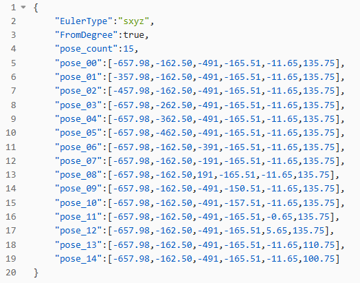
The calibration board is mounted at the end of the robot arm, and the pose JSON file below is used. Nevertheless, a disparity exists between the extrinsic calibration outcomes achieved by the user and the real-world results.
3.2 Cause
In the user-input pose JSON file, the translation components x, y, and z are all in meters, whereas the required unit in the sample is the millimeter. This discrepancy has led to calculation errors.
3.3 Solution
Modify the unit of x, y, and z translation components in the JSON file to the millimeter. Besides, corresponding unit explanations have been added to the code and README file, and an updated sample of the pose.json for calibration has been provided, aiding users in creating pose files with enhanced clarity.
Alternatively, in the sample code, modify the function ‘extrinsicTotransval’. The following screenshot illustrates how to convert measurement units from millimeter to meter:

4. Capture the robot’s flange pose in the base reference frame to avoid incorrect extrinsic parameter calibration results
4.1 Issue
When users interact with the robot teach pendant to display poses, they encounter various available reference frames. For instance, considering ABB robots, there are four selectable reference frames, and each yields distinct robot poses. Moreover, within the robot settings, one can specify whether to display the tool’s pose (such as a suction cup or gripper) or the flange’s pose.
4.2 Cause
The calibration function provided by Mech-Eye SDK aligns with Mech-Vision’s approach: by default, both utilize the robot’s flange pose and the base reference frame. Any discrepancies between the two consistencies can result in inaccurate calibration outcomes.
4.3 Solution
Confirm that the robot’s reference frame is the base reference frame. If no tool is configured, the output pose will be the flange’s pose.
5. Inconsistent Euler angle type and order lead to incorrect extrinsic parameter results
5.1 Issue
The user enters the Euler angles in the order of Rx, Ry, Rz, which is inconsistent with the ABB robot’s rzyx Euler angle type, resulting in an error.
5.2 Cause
The ABB robot requires the EZ-EY-EX sequence for correct Euler angle input, but the user provided angles in the reverse sequence, resulting in mismatched outcomes.
5.3 Solution
-
Adjust the Euler angle sequence to align with the table below.
-
Users can also directly compare the converted quaternion from the Halcon sample to ensure alignment between the input quaternion and the actual robot pose quaternion. If the desired Euler angle type is not supported, calibration can be performed using the directly input converted quaternions.
-
Refer to the table for the Euler angle display sequence for popular robots:
| Brand | Teach pedant display | Sample input sequence |
|---|---|---|
| Kawasaki | O-A-T | Z-Y’-Z’'(rzyz) |
| ABB | EZ-EY-EX | Z-Y’-X’'(rzyx) |
| Rokae | A-B-C | X-Y-Z(sxyz) |
| FANUC | W-P-R | X-Y-Z(sxyz) |
| KUKA | A-B-C | Z-Y’-X’'(rzyx) |
| UR | Rx-Ry-Rz | X-Y-Z(sxyz) |