Background introduction
- Introduction on using Mech-Eye API: Mech-Eye API
- Sample usage guide (C++): C++ (Windows)
- Detailed interface information: Mech-Eye C++ API
This post mainly explains the methods of getting intrinsic parameters and their meanings, as well as how to use these parameters to obtain point clouds through depth maps.
Methods of getting intrinsic parameters and their meanings
Get intrinsic parameters
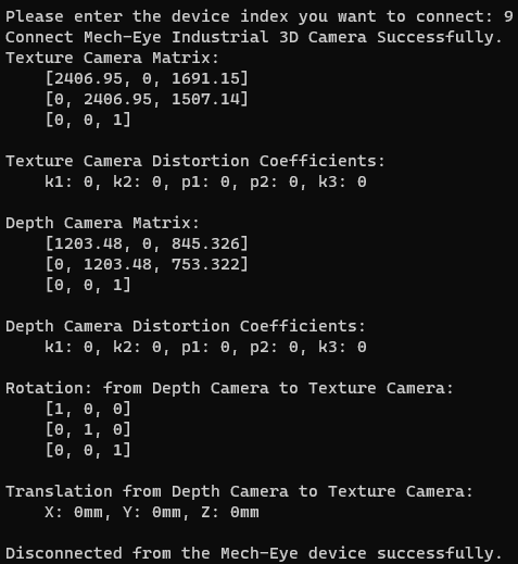
As described in the sample usage guide above, you can compile the sample. By running the “GetCameraIntri” sample and connecting a Laser L Enhanced camera, you can obtain its intrinsic parameters. The image below is an example image. For specific intrinsic parameters’ information, it needs to be obtained after connecting the camera.
Get intrinsic parameters’ interfaces
The sample “GetCameraIntri” gets and prints a camera’s intrinsic parameters.
Intrinsic parameters’ meaning
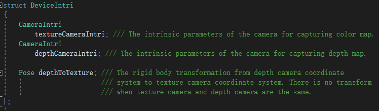
In the Laser L Enhanced V3S and LSR V4 binocular cameras, “Depth Camera Matrix” represents the intrinsic parameters of the main camera, while “Texture Camera Matrix” represents the intrinsic parameters of the sub-camera. The matrices are arranged as follows:
[ fx, 0, cx]
[ 0, fy, cy]
[ 0, 0, 1]
Here is a breakdown of the individual parameters:
fx: Horizontal (X-axis) focal length of the camera, measured in pixels.
fy: Vertical (Y-axis) focal length of the camera, measured in pixels.
cx: Horizontal coordinate of the principal point on the image, measured in pixels. The principal point represents the optical center of the camera, where the optical axis (the central axis of the camera) intersects the image plane. cx indicates the position of the principal point in the horizontal direction.
cy: Vertical coordinate of the principal point on the image, measured in pixels. cy indicates the position of the principal point in the vertical direction.
It is worth noting that the Laser L Enhanced V3S outputs undistorted 2D images by default and does not have an external third texture camera. Therefore, both its distortion coefficients and parameters for an external camera are left empty.
Sample: depth map to organized point cloud conversion
Usage of the sample
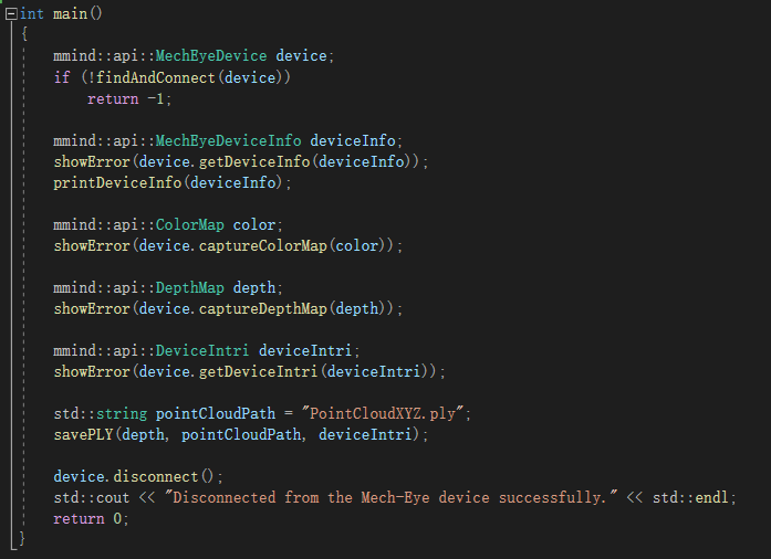
Run the sample “CaptureCloudFromDepth”, connect the camera, and you will get the point cloud generated from the depth map.
Detailed description of the sample
The main program utilizes the savePLY function to input the depth map, point cloud storage path, and camera intrinsic parameters, ultimately saving the point cloud data.
The savePLY function can generate organized point clouds from the depth map. Here, ‘m’ and ‘n’ correspond to the coordinate values in the depth map, and the resulting organized point cloud corresponds to the depth map.
1. Create a pcl::PointXYZ object to represent the point cloud data.
2. Resize the point cloud to match the size of the depth map.
3. Iterate over each pixel of the depth map and perform the following transformations:
a. Get the depth value (in millimeters) of the current pixel.
b. Convert the depth value from millimeters to meters by multiplying it by 0.001 (if the point cloud result is required in meters).
c. Perform transformation based on the camera intrinsic parameters (intri.depthCameraIntri.cameraMatrix):
- Set the Z-coordinate of the point to the converted depth value.

- Set the X-coordinate of the point using the formula: x = (n - cx) * d / fx
where:
x = X-coordinate of the point
n = Column number of the pixel
cx = X-axis center point of the camera intrinsic parameters
d = Depth value (converted to meters)
fx = X-axis focal length of the camera intrinsic parameters (cameraMatrix[0])

- Set the Y-coordinate of the point using the formula: y = (m - cy) * d / fy
where:
y = Y-coordinate of the point
m = Row number of the pixel
cy = Y-axis center point of the camera intrinsic parameters
d = Depth value (converted to meters)
fy = Y-axis focal length of the camera intrinsic parameters (cameraMatrix[1])

4. Create a pcl::PLYWriter object to export point cloud data to a PLY file.
5. Use the write function of the PLYWriter object to save the point cloud data to the specified path.
6. Display the number of data points in the point cloud and the storage path information.

“depth.at”:
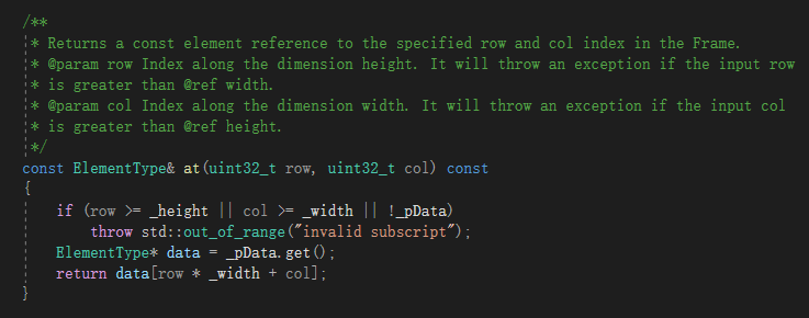
“pointCloud.at”:

Key points
In this post, the depth map is the one after distortion correction. Therefore, there is a linear transformation between the depth map and the point cloud. However, there is a distortion relationship between the depth map and the original 2D image. For a binocular camera, the 2D image is the one after distortion removal.
Reference information
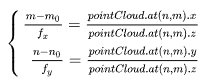
Relationship between camera pixels and point cloud: A three-dimensional point P (X, Y, Z) corresponds to the camera’s two-dimensional image point (x, y).
In other words, the three-dimensional spatial point (pointCloud.at(n, m).x, pointCloud.at(n, m).y, pointCloud.at(n, m).z) mentioned previously is imaged on the camera as (n, m).

According to the principle of similar triangles, it can be known:
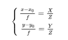
Combining with the previous context, it can be represented by the following equations: