An introduction of ToF
Principle
Time-of-Flight (ToF) is a method for translating information in the time dimension into information in spatial dimensions. As we all know, Distance = Velocity * Time, and light’s velocity in vacuum is 299,792,458 m/s. Therefore, by measuring the time it takes for light to travel to an object and back, we can measure how far light travels, and how far away the object is. This is the basic idea behind a time-of-flight camera.
Many animals are born with such ability to measure distances and the most widely-known are bats and dolphins: they can gauge how far an object is by emitting sound waves in certain frequencies and receiving subsequent echoes.
The ToF laser scanner, aka the LIDAR system and the laser radar, measures distances in the time domain: the distance between a sensor and an object can be calculated by the time difference between the emission of laser and its return to the sensor.
Advantages
- The method measures time, ensuring calculation accuracy regardless of the distance being measured.
- The method works well under interference and shades and it is immune to objects’ different grayscale values and features.
- The method is capable of measuring distances up to hundreds of meters, adjustable through frequency tuning of emitted pulses.
- The method can measure very short time delays, achieving real-time frames per second (fps) ranging from dozens to hundreds.
Disadvantages
- Theoretical accuracy is lower than that of a structured light system when the distance is shorter than 10 m due to complex designs, physical properties of light, and the measurement principle itself.
- The method lacks color data.
- The method is easily affected by reflections.
- The method produces low resolution images (VGA).
Applications
Activities in large spaces, like self-driving cars, car range finders, visual safety systems, etc.
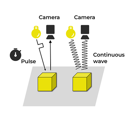
A schema of ToF:
Two ToF methods: dToF and iToF
To modulate, ToF 3D cameras use either dToF (pulsed modulation) or iToF (continuous wave modulation).
Pulsed modulation ToF
Pulsed modulation ToF is also known as dToF (direct time of flight), and its most widely-known application is laser radar scanners.
Principle
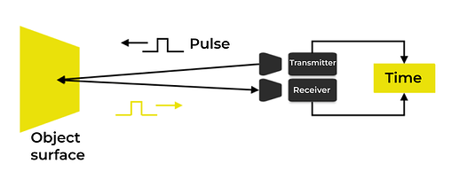
dToF sensors emit laser pulses and then measure the time it takes for the emitted light to come back. This method requires high-speed detection devices and it is applicable to measuring large objects.
Advantages
- Easy to use.
- High response speed.
- Resistant to ambient light and multipath interference.
Disadvantages
- The method is expensive.
- The emitted pulse width time should be within picoseconds.
- The power of emitted light should be in the millions of Joules range.
- The sensor, equipped with super HDR, requires picosecond-level time resolution.
- The time it takes for the emitted light to come back is short, leading to lower accuracy and depth resolution.
Applications
- Area array measurement: The dToF system in iPad Pro (2020) uses a Single Photon Avalanche Diode (SPAD) array, making it possible to accurately measure distances with low power.
- Point array measurement: Laser radars in Google’s self-driving cars.
A schema of dToF:
Continuous wave modulation ToF
Continuous wave modulation ToF is also known as iToF (indirect time of flight).
Principle
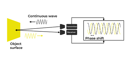
This method measures distance by collecting reflected light and discerning the phase shift between emitted and reflected light. It is highly accurate so it is suitable for measuring small objects.
Advantages
- Higher accuracy compared to dToF.
- Lower requirements for emitted light standards.
Disadvantages
- Measurement distances are limited.
- The method is susceptible to ambient light interference, such as sunlight and reflections.
- Multiple sampling and integration steps are required for accurate measurements.
- Longer measurement time is necessary.
- Blurs are likely to occur when dealing with limited FPS or measuring moving objects.
Applications
- Continuous wave iToF area array chips in SONY IMX570.
A schema of iToF:


