Currently, I have a project in my hands where I am trying to segment a couple of metal plates that sometimes overlap each other. The idea is to find the highest plate and therefore I need to separate them first, otherwise, the program is going to recognize them as one piece.
First, I set up a standard Mech Vision program where I take an RGB image and point. Then, I added a couple of steps such as ‘calculate normals’, ‘point filter’, ect. where I process this data. After all these steps, I noticed the plates were not segmented correctly. I tried to change every parameter that I could in Mech Vision and Mech Eye but I was not able to get any kind of good result. I tried to increase the point filter, but then I noticed If I increased the point filter parameters to much, I started to lose crucial information about the plates. I also changed the way normals are calculated but I had no luck. In Mech Eye, I changed the ‘Point Cloud Processing’ parameters but I had the same result.
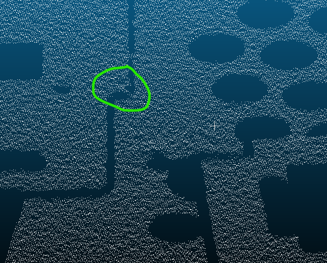
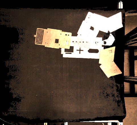
Finally, after I had a look at the point cloud using CloudCompare, I found these small bridges. I concluded the program is assuming (and well) they are connected and therefore they are one piece. Why can not they be removed by the point cloud filter? Has someone already found this issue before? How did you fix it?
In this scenario, we recommend employing deep learning for instance segmentation. Given that the metal board is thin, obtaining the highest layer is challenging, and separation becomes difficult. Even if separation is achieved, performing 3D point cloud matching is arduous due to potential mismatch misalignment.
The bridge, possibly caused by the distortion, exposure or algorithm issues. To investigate the actual reason, could you please save the image as an mraw file and send to us? This will enable us to examine the grey information and determine the root cause.
The Use the Instance Segmentation Module in the user manual shows an example of using an Instance Segmentation module and training a model to segment different types of objects, please refer to it for detailed information and instructions.
Thank you for your suggestion. We initially thought about that possibility but it goes against one of the custommer requirements, so we discarded that option.
No worries. Could you please inform us of the specific customer requirements we are currently unable to meet? Typically we use deep learning for instance segmentation to address issues similar to yours. We would like to know the challenges that cannot be resolved through deep learning, as this could be valuable information to enhance our product. Thank you.
Sure Huan. (To be more clear, I am going to create a fictional case). Let’s assume our customer has a car factory and today is producing the parts to do a door. To produce the door, he needs the parts A,B,C and D. The parts will go through a conveyor and they have to be identified, to be then put in a specific place. So, we want to find the closest match between the metal plate on the conveyor and the dataset (A,B,C,D), so then we can put the part in the correct place according to each specification. But then, the next day, the customer starts producing parts E,F,G and H to do the windshield. In the next, part I,J,K, L, M, N and O to make the seat. And so on. The dataset is going to be always changing and the customer wants something flexible. A program that allows him in 5 seconds to change the dataset to something new without needing to go inside a program (such as the DLK, as you mentioned). This logic was already developed by us. I created this issue because he mentioned some parts may be overlaped in the conveyor and we need to take care of it.
Hi Miguel, based on our understanding, deep learning can meet the requirements of your case through switching the model packages in Mech-Vision.
The basic usage of deep learning involves:
First, in the early stages of the project, train on different objects in Mech-DLK to generate corresponding deep learning models.
Then, import the deep learning models into the Mech-Vision project to assist in recognizing objects (Use the “Deep Learning Model Package Inference” Step in Mech-Vision) .
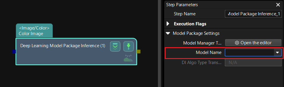
For different workobjects, you only need to switch the model package in the “Deep Learning Model Package Inference” Step, as shown in the figure below. Therefore, when using the deep learning, only the model training before the project will take some time. After importing the deep learning model, the runtime during project execution will not differ significantly compared to point cloud processing. So we think that deep learning may be suitable for the requirements of your case.
We’ve considered using the DLK but the products we need to pick will be random. This means we will not have any dataset to train our model with. We may be able to train it to detect any shape, given the contrast with the conveyor is good. Since the products can sometimes overlap each other, I doubt this will be very reliable in its segmentation. That’s why we have decided not to use a DLK approach for this solution. I hope this makes it a little clearer.
Is there no way to isolate these ‘bridges’ to filter them from the cloud? Or do you have suggestions for Mech-Eye parameters we should try?
Our colleague is checking the file and will get back to you soon. Thanks again for your patience.
Besides, for the segmentation problem, our technical support engineer might be able to provide you with more assistance. Is it ok for us to share your contact information with our technical support engineer?
2、Is the current issue the inability to differentiate between steel plates?What is the current firmware version of camera you are referencing ?
3、I suggest you upgrade the firmware to the latest version and set the Stripe Contrast Threshold parameter to 10 to see if it helps with the adhesion issue.
Hey Liuqing,
1- The bridges only occur when I try to segment the plates using the ‘Point filter’, therefore you can not see them in Mech-Eye. This step removes most points that are binding the parts together but it leaves some points in the point cloud, like the ones in the first picture. Then, when I cluster, some parts are classified as one because of these small ‘bridges’ which are unremoved points left behind from the ‘Point filter’.
2- Yes, we found problems when they overlap each other. The firmware version is 2.2.2 638b4629f (LSR L)
3- Yes! That parameter improves the segmentation. But after some tests, the problem remains.
I created a fresh new set of files this afternoon so you could analyze better the issue. The first set of photos (case 0) it’s a case when the bridge appears. The second its when I was able to segment the plates better. In both the conditions remained the same and I just press Run one after the other, so there are 2 seconds a part.
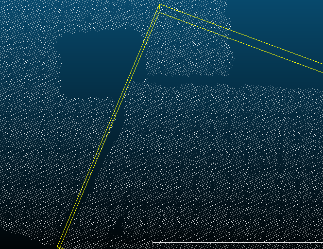
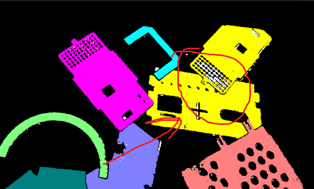
Then, use Steps like “Point Cloud Clustering”, “Get Highest Layer Clouds”, and “3D Matching”, and the point clouds can be successfully clustered, as shown below.
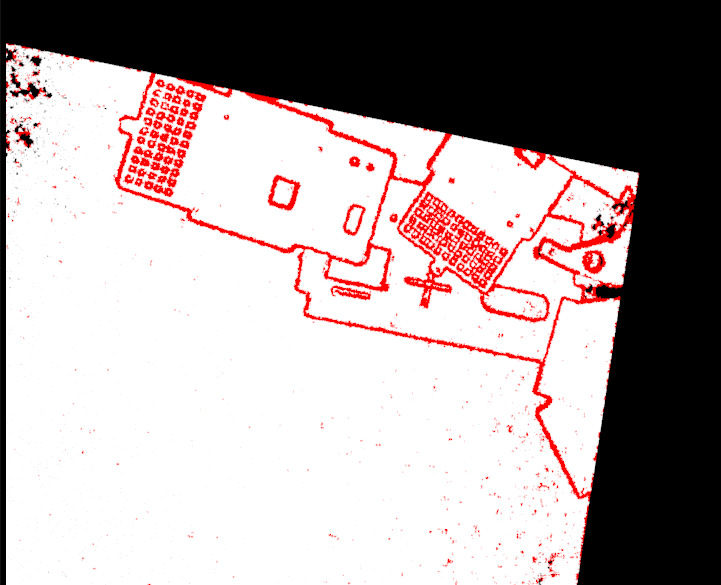
In the Mech-Eye Viewer, adjust the exposure of the color image to ensure it is clear enough, avoiding overexposure and underexposure. Currently, your color image is overexposed.
Then, adjust the Mech-Eye parameter of the “Capture Images from Camera” Step in Mech-Vision: Select “External Color Image” for the “2D Image Type” parameter. For more information on this parameter, please refer to “2D Image Type” in this link: Mech-Eye parameters.
Hey Huan,
I think your corrections did the trick so your help was very valuable. In your opinion, since it may compromise the matching, do you think it’s possible to save the grid in one of the parts? I tried to play with the point filter but the parts ended up together again (Last photo)