This article discusses gripper design in the logistics industry. It covers essential aspects of designing grippers, explaining the selection of standard components, designing vacuum systems, and creating custom gripper parts.
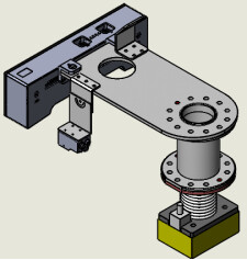
1. Gripper Main Structure
-
Ensure the Main Structure is Sturdy: The gripper’s main structure must be robust and reliable. If necessary, perform stress simulations. It’s not recommended to use aluminum profiles with poor rigidity for certain load-bearing components.
-
Add Cushioning Devices: Installing cushioning devices in the vertical direction (Z-axis) of the gripper provides protection for both the product and the gripper. For larger grippers, consider the case where one side of the gripper undergoes pressure during single-box handling, preventing the gripper from fully recovering after being pressed down.
-
Consider Rotation: When specific gripping or placement orientations are required, it’s generally undesirable for the object to rotate during the suction motion. Therefore, when choosing gripper adapters, anti-rotation features should be taken into account. If the incline angle of the object’s suction surface is unknown, an adapter should be added at the gripper’s end to accommodate the aforementioned incline angle.
2. Nozzle Selection
- Use life of bellows suction cups (accordion suction cups) is superior to sponge suction cups.
- Generally, larger inertia leads to poorer gripper motion: Grippers may exhibit worse motion when handling materials with larger inertia.
- Prioritize softer material for suction cups (such as silicone bellows suction cups): This ensures better adherence between the suction cup and the cardboard when gripping. However, if the gripped box is heavy, the supporting part of the bellows might be too soft, leading to potential slipping. In such cases, selecting a harder suction cup is necessary.
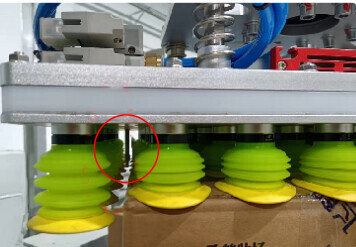
(In the image below: 1. Gripper body; 2. Nozzle; 3. Cardboard)
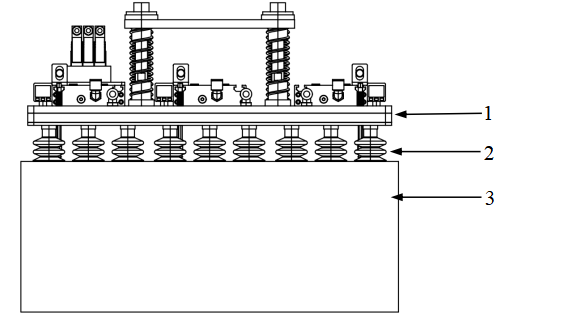
- For workpieces with high permeability (prone to being lifted by suction), consider choosing smaller suction cups.
3. Vacuum System
- High flow picking systems generally use fans. To balance the flow inside the suction cup’s check valve and optimize suction cup performance, it’s recommended to equip the fan with a pressure relief valve.
- In cases of significant air leakage leading to low suction force, enhance the vacuum source performance and increase the effective cross-sectional area of the distribution pipe.
- The distance between the vacuum generator and the suction cup as well as the size of the air pipe between them affect the suction cup’s adhesion force. In general, try to minimize the distance between them.
- Considering extreme conditions like power outages, choose supply valves with normally closed or self-holding functions. For breaking valves, use throttle valves to regulate the breaking flow.
4. Sensor Design
-
The number of drop detection sensors (specifically the “photoelectric sensor + probe” configuration) should be determined based on the potential dimensions of cardboard boxes and the gripping methods used. Common gripping methods include the following two types:
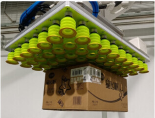
(In the image below: 1. cardboard box; 2. sensor positions; 3. suction cup)
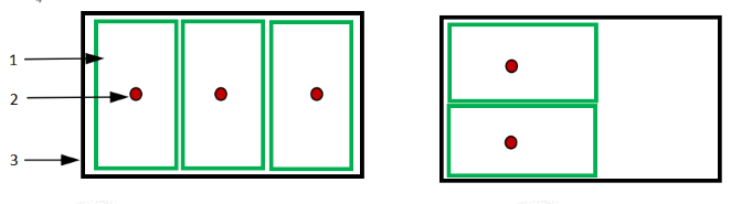
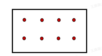
The positions and quantity of sensors should be considered in the context of the two gripping methods illustrated above, as shown in the image below.
-
Due to the variety of cardboard types and varying corrugated cardboard hardness at the site, integrators typically set the sensor light to stay on when the suction cup is not in operation. Since our software needs to detect high-level signals, it requires the addition of a relay to invert the signals. Alternatively, the robot’s internal inversion function can also be utilized.
-
Sensor placement should be based on the planned suction cup gripping path and the smallest cardboard box. However, caution should be taken as, in some cases, sensors might fall on the edge of the cardboard. During robot movement, slight vibrations could cause the sensor to return to its original position, triggering incorrect drop commands. To avoid this, consider adding extra sensors as needed.
-
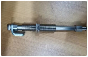
For components of sensors with relative motion, fatigue life should be should considered. This issue can be addressed through structural and material considerations. For example, the moving parts in the probe (as shown in the diagram below) could be made of stainless steel. The mounting sheet metal for sensors should not be thinner than 3 mm.
5. Barcode Reader Installation
-
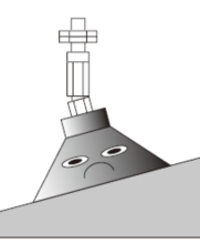
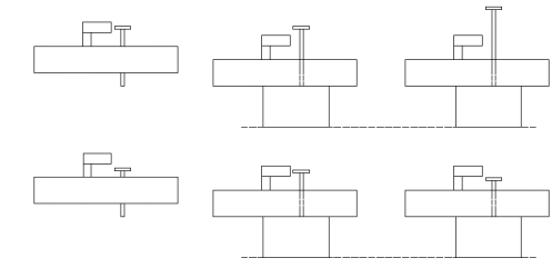
Considering the slight compression of the suction cup (common in corrugated or sponge suction cups), in scenarios where the robot is required to scan the barcode after gripping the carton, it is generally necessary to maintain a certain distance between the barcode and the top of the carton (recommended range: 70 mm to 150 mm). Otherwise, as shown in the diagram below, the scanning success rate will be affected due to the gripping pose.
-
For scenarios where both speed and field of view are critical, dynamic barcode scanning is preferred over static scanning.
-
In the logistics industry, barcodes are mostly one-dimensional. The accuracy of the barcode is typically within 0.2 mm to 0.5 mm. Therefore, it is generally required that the barcode printing quality is at least Grade B to ensure effective scanning results.
-
Common arrangements of code readers are shown in the diagram below:
-
Fixed installation: Mostly used in scenarios where it is placed alongside conveyor belts or in coordination with robots to scan logistics and product codes.
-
Installed at the end of a robot arm: Under the robot’s control, it can achieve multi-degree-of-freedom and multi-pose code scanning. When products are covered with transparent materials or when reading codes through acrylic, attention should be paid to nearby light sources forming spots near the barcode, which may affect the success rate of code reading.
-
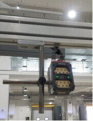
Installed on the robot’s main arm: The code reader scans the products picked by the gripper at the end of the robot arm during the robot’s movement. The biggest advantage of this method is that it can integrate the scanning time into the robot’s motion cycle, which helps improve the overall production efficiency of the assembly line.
-
-
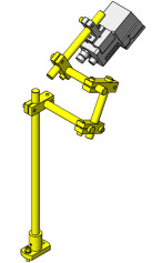
When designing the code reader bracket, ensure a certain amount of adjustment margin, as shown in the diagram below, to allow the code reader to be adjusted in multiple directions. In practical use, the bracket shown below can be simplified based on the actual requirements.

6. Suction Cup Accessories
-
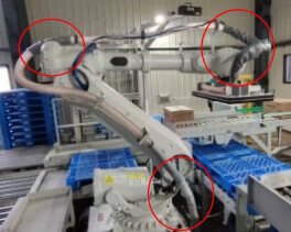
The length of the suction pipe’s free section should be carefully considered in relation to the robot’s 6-axis motion to prevent bending and other issues.
-
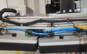
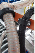
Taking into account the pneumatic tube and other pipelines, a rational layout should be planned to avoid mutual collisions and friction during movement, which could lead to air leakage.
-
In scenarios where accessories experience significant force or intermittent impacts, special attention should be given to prevent sudden attachment breakage during operation.
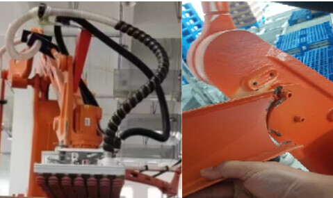
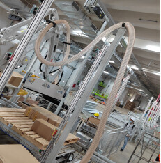
-
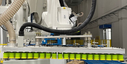
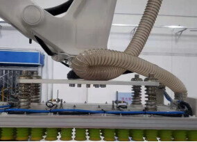
The overall direction of the air duct should be made as smooth and flexible as possible, taking into full account the impact of the robot’s operation at different stations. If necessary, the air duct bracket height can be elevated (as shown in the diagram below), in which case the air fan’s air supply volume and pressure should be considered.
-
The points where the air duct directly contacts the robot body, gripper, or other parts should be wrapped with wear-resistant fabric or covered with abrasion-resistant tubing to increase the air duct’s lifespan.