For the introduction to gripper offsecting and its advantages, you can also refer to docs:Gripper Offset
Introduction to the Concept of Offsetting
Gripper offset refers to a specific spatial arrangement or structural form of a gripper:
-
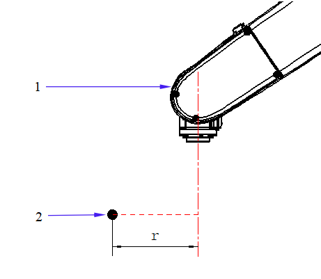
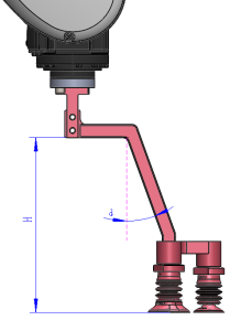
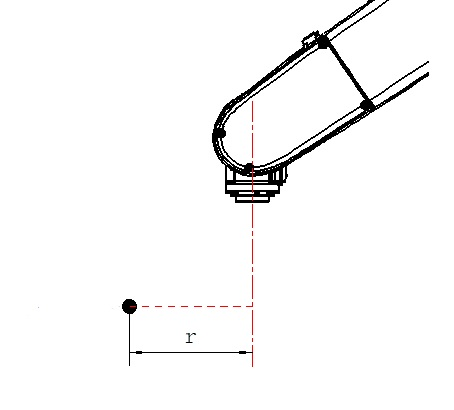
Spatial Coordinate Offset in the Horizontal Direction: This involves positioning the robot’s flange center and the pick point at a certain horizontal distance (offset radius) in the direction of the plumb bob when the robotic arm picks the workpiece, as shown in the diagram below (1: robotic arm, 2: pick point, r: offset radius).
-
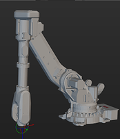
TCP Orientation (Angle) Offset: In certain necessary scenarios, the gripping surface of the gripper’s end effector can also be oriented at a specific angle relative to the robot’s flange mounting surface, increasing the offset magnitude, as illustrated in the diagram below (1: robotic arm, 2: gripper).

Purpose of Offset: Avoid Robot Wrist Singularities, Improve Pick Rate, and Expand Radius for Picking
Practical experience has shown that in specific working conditions, gripper offset significantly enhances the entire picking system.
1. Avoiding Wrist Singularities
Problem Description: In real-world scenarios, objects to pick arrive in various forms, and their orientations cannot always be controlled. Without offset, the planned picking pose might lead to robot singularities.
The robot is in a wrist singularity state when:
- Axes 4 and 6 coincide (are parallel), meaning Joint 5 is at 0°.
- The rotation of Axis 4 can compensate for the rotation of Axis 6.
- This situation may result in rapid axis rotations.
2. Increase the Success Rate of Picking in Limited Spaces (i.e., Improve Pick Rate)
Problem Details:
Customers demanded a high pick rate, but there were certain limitations:
- The incoming objects had narrow spaces or limited local spaces (for example, deep bin picking).
- The gripper’s end effector (either pneumatic or electric) had large external dimensions or a peculiar shape (with various protrusions).
- The items are often positioned in challenging locations (such as corners) that are difficult to pick.
If a non-offset gripper is used, the actuator and its fixtures would interfere with the surrounding environment (such as the bin walls) in various ways.
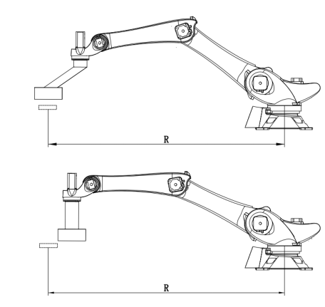
3. Expand the Radius for Picking
- When there is a mismatch between the robot model and the actual workstation’s requirements for the picking radius, gripper offset can be used to extend and compensate for the picking radius.
Project Cases
Project Case 1: Arbitrary Object Picking Project, Offset to Avoid Wrist Singularities
Project Requirements: The robot is tasked with sorting a massive quantity of products from a bin. The products can have various shapes, orientations, and positions upon arrival.
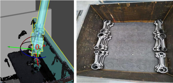
Problem: During actual operation, there is a high likelihood that the incoming products’ poses align with the robot’s singular points (wrist singularities), as shown in the diagram below.
Solution: Gripper offset, allowing the robot’s flange spatial position to not align with the pick point along the same plumb line.
- Considering the height of the bin, it is essential to avoid interference between the gripper and other objects or the basket walls during grasping.
- Therefore, an angle ‘a’ deviating from the vertical line is set to avoid wrist singularities.
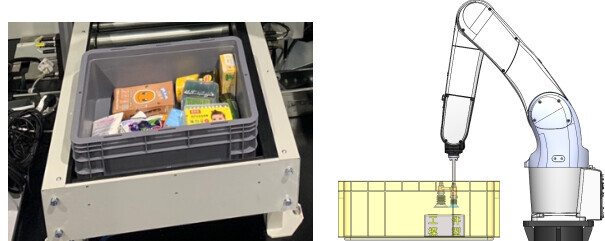
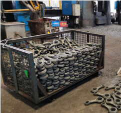
Project Case 2: Connecting Rod Picking Project, Offset for Bin-Corner Picking
Project Requirements:
- Use the vision system to calculate the pick points of the rods in the bin, and use a 6-axis robot to pick and place them in the machining center.
- The bin is deep (length * width * height: 1000mm * 800mm * 750mm).
Challenges:
- The depth of the bin increases the difficulty of picking.
- Varied orientations of the rods due to placement and transportation reasons.
- Non-offset gripper design: Due to multiple functional requirements for the gripper, its complex shape and large size.
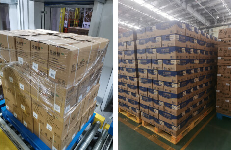
- When a rod is in the corner of the bin, the gripper cannot pick it properly, leading to a high rate of unpicked rods.
- The left image shows the limitations encountered by the gripper in the corner, and the right image shows the rods left unpicked after completion.
Customer’s initial version of the gripper design:
- Extended arm to ensure that the camera does not collide with the bin wall when picking the bottommost rods.
- The buffer device can accommodate errors in the Z direction of the camera.
- The sensor primarily serves the purpose of detecting drops.
- One end of the gripper has two fingers, while the other end has three fingers, allowing effective picking of entire individual rods.
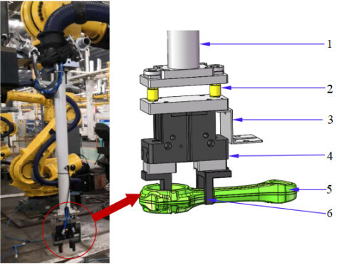
① Extended arm | ② Buffer device | ③ Sensor mounting base | ④ Holding cylinder | ⑤ Rod | ⑥ Gripper fingers
Solution:
The gripper underwent offset adjustments, as shown in the green section in the image below, to facilitate picking the rods in bin corners.
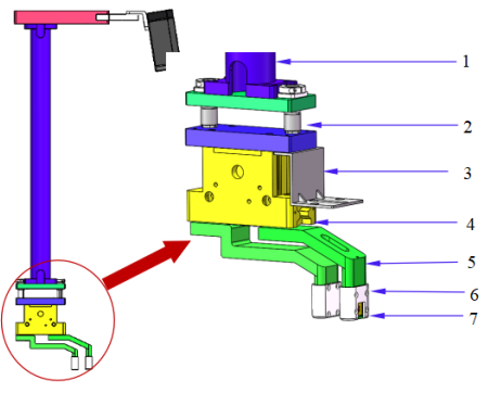
① Extended arm | ② Buffer device | ③ Sensor mounting base | ④ Holding cylinder | ⑤ Gripper fingers | ⑥ Finger covers | ⑦ Sensors
Disadvantages of Gripper Offset
1. Reduced Robot Payload
It is necessary to check the actual available payload of the robot based on the robot’s own payload curve and the offset amount of the gripper.
Here is a graph showing the variation of end-effector payload for a specific robot:
- Lxy represents the offset along the X/Y axes in the flange coordinate system.
- Lz represents the offset along the Z-axis in the flange coordinate system.
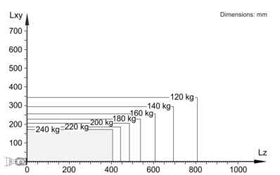
When the offset radius exceeds 250mm, the payload significantly decreases. However, if the offset radius is less than 170mm and increased along the Z-axis to 400mm, a relatively high payload can still be maintained.
2. After introducing offsets, new constraints have been introduced for picking and placing products in specific poses.
In real-life scenarios, the objects to pick are non-symmetric at 180 degrees along the Z axis, and there are specific orientation requirements for picking or placing specific objects. For instance, during outbound logistics, it is often necessary for the barcode on cardboard boxes to face outward for easy manual scanning and picking.
If it is required that a specific edge of the gripper aligns with a specific surface of the object, gripper offsets can interfere with successful picking or placing when the robot operates at the extreme positions within its reachable range.
For example, if the robot needs to rotate 180° in the 6th axis when picking a workpiece (as shown on the left side of the image), the robot’s 6th axis center point needs to move a distance of 2r. Especially near the robot’s maximum operating radius, this can easily lead to picking failures.
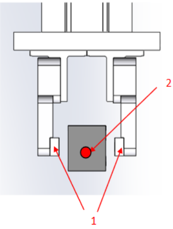
3. It is challenging to determine the TCP value at the gripper’s clamping point.
The TCP at the gripper’s clamping point is the spatial symmetric center of the two clamping blocks, as shown in the diagram below (① clamping block | ② gripper’s clamping point TCP).
After the offset, setting the tool TCP at the robot end becomes quite difficult for users. It is not possible to accurately measure the offset value; instead, users can only teach the TCP of the gripper’s clamping support surface (NC surface) center using the robot’s built-in four-point or six-point method.