When using a camera in extreme environments, high temperatures, welding slag, and other factors can damage the camera, affecting the imaging quality and the camera’s lifespan.
To solve those problems, you can use camera protective mechanisms.
This article presents the design knoweldge of camera protective mechanisms for welding scenarios, high-temperature environments, and low-temperature environments respectively.
1. Design of Camera Protective Mechanisms in Welding Scenarios and Dust Scenarios
1.1 Problem Description
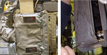
- When operating in welding scenarios and dust scenarios, the camera is exposed to the welding and dust environment for long periods. The camera body and lens will accumulate a significant amount of welding slag, spatter and dust, which will greatly affect the point cloud imaging.
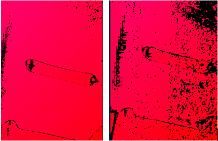
- The following picture is a comparison of the point clouds taken by a camera at a project site before and after the accumulation of welding slag. The point cloud quality in the latter is noticeably degraded.
1.2 Design of Camera Protective Mechanisms in Welding Scenarios and Dust Scenarios
1.2.1 Solution One: Applying a Tempered Film
- Protect the camera lens by applying a tempered protective film. The technical specifications of the tempered protective film are shown in the table below.
| Property | Value |
|---|---|
| Refractive index | 1.51 |
| Softening temperature | 820℃ |
| Bending strength | 1.542 |
| Expansion coefficient | 0.035–0.055% |
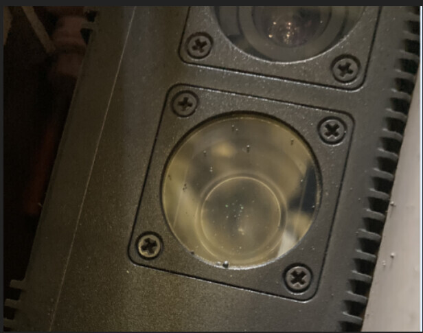
The thickness of the tempered film has a significant impact:
- When the tempered film is thick, welding operations can easily lead to the accumulation of welding slag at the edges of the protective film. When applying the tempered film, air bubbles may be trapped between the film and the camera lens, and they cannot be manually removed. This can lead to blur spots resembling water ripples, as shown in the picture below.
- The thinner the tempered film, the poorer the protection, but the higher the point cloud quality.
- Through multiple tests, we found that the optimal thickness for the tempered film is between 0.22 mm and 0.33 mm.
In practice, it is recommended to replace the tempered film periodically in accordance with the production operation cycle.
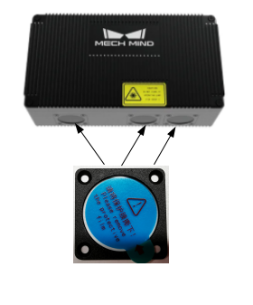
It is not recommended to solve the problem of welding slag accumulation and dust accumulation on lens by replacing the entire lens (as shown in the image below) for the following reasons:
- Repeatedly disassembling the lens fixing bolts can easily lead to disengagement or loosening.
- Because the on-site environment is much worse than the in-factory assembly environment, repeatedly disassembling on-site can easily cause dust to enter the camera, affecting its lifespan and the point cloud quality.
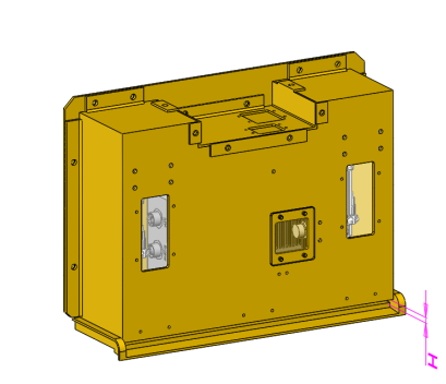
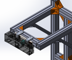
1.2.2 Solution Two: Semi-enclosed Camera Protective Cover
Use movable hinges to connect the bottom of the protective cover (at the camera lens area) to the side walls of the cover. Open the protective cover when taking photos and close the camera cover after image-capturing to ensure that the camera is not affected by dust in the environment, and splashes like welding slag during on-site welding operations.
1. Important Considerations for Designing the Semi-enclosed Protective Cover
Consider the following factors:
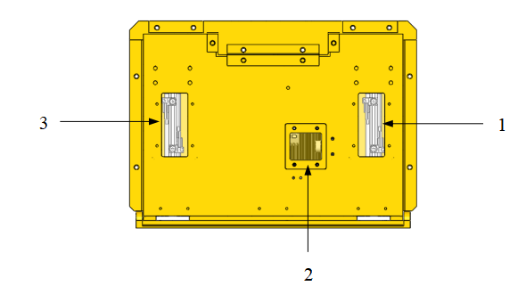
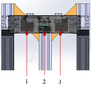
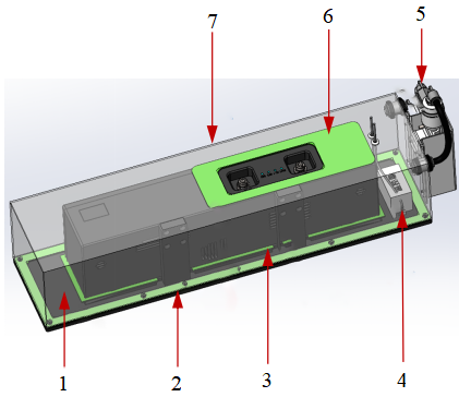
(1) The camera protective cover should be easy to disassemble and maintain, especially for facilitating manual observation and adjustment of internal regulating valves, switches, and indicator lights.
In the image below: 1, 3 are adjustment windows for magnetic switches, and 2 is an adjustment window for the speed control valve.
(2) For parts such as hinges, wire pass-throughs, and air pass-throughs, enhance the protective and sealing performance of the cover.
(3) For some environments with harsh conditions, consider wrapping the camera protective cover with a protective garment. The material of the protective garment can be customized based on the on-site temperature (or customer requirements). After the camera protective cover has been in use for a certain period, it requires regular maintenance and cleaning of welding slag and dust. If corrosion occurs, maintenance and replacement are necessary.
2. Protection of Camera Cables in the Semi-enclosed Protective Cover
(1) For cameras installed by EIH, during the initial design phase, you should take into account both the robot’s end camera cables and the protective cover cables based on the actual situation. They can be designed and laid out together, or they can be fixed and bundled separately.
(2) Cables for the camera, cylinder, and others can be protected with customized flame-retardant conduit covers. It is preferable to use a side-opening design, where any part of the entire conduit cover can be opened from the side, making installation and maintenance more convenient.

(3) When necessary, use a balancing hoist to ensure that the camera cable conduit cover is evenly stressed, reducing collisions and friction with other conduits, and making installation easier.
(4) For easy disassembly and maintenance, consider using aviation connectors (often referred to as “aviation plugs” or “aviation sockets”). This facilitates quick replacement and repair of the cylinder signal cables.
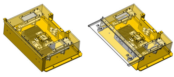
1.2.3 Solution Three: Fully Enclosed Camera Protective Cover
In scenarios with harsh environments, consider using a fully enclosed camera protective cover. The fully enclosed camera protective cover is made from sealed sheet metal, creating an independent space that can meet the camera’s image-capturing requirements.
1. Important Design Considerations for the Fully Enclosed Protective Cover
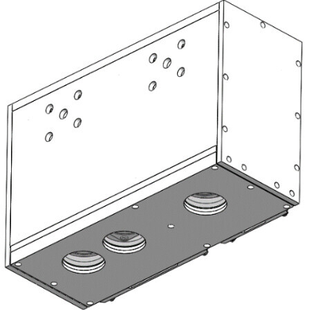
(1) Taking into account the lifespan of the camera protective cover, the bottom can be designed with a drawer structure for easy replacement. In the picture below: 1, 2 represent the drawer structure and 3 is the fastener.

(2) To minimize the impact on measurement results, the glass window should be as close as possible to the camera window, with its surface as parallel as possible to the camera window. During assembly and use, avoid any force that may cause deformation.
(3) Choose flat glass with high surface evenness for the glass window, which should meet the requirements in the table below. Recommended models: Chengdu Guangming’s K9 and H-K9L (K9 is eco-friendly), and Schott BK7 and N-BK7 (BK7 is eco-friendly) of Germany.
| Property | Value |
|---|---|
| Thickness | 1–3mm (as thin as possible with high surface evenness) |
| Refractive index | 1.52 |
| Abbe number | 64.2 |
| Coating | Double-sided AR coating (visible light transmittance ≥98.5%) |
2. Design of Camera Protective Cover in High-Temperature Scenarios
2.1 Increase Airflow Speed on the Camera’s Outer Surface
Suitable scenarios: Areas where the temperature is not too high (with the surrounding hot air radiating at around 40℃) and where there’s relatively good ventilation.
1. Use Air Knives or Nozzles for Air Blowing
Commonly used mechanisms like air knives and nozzles are shown in the picture below.
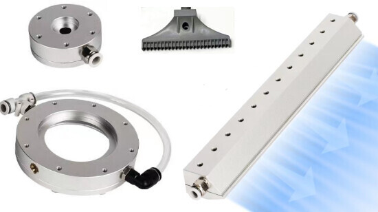
Disadvantages: Requires on-site compressed air, produces high noise, and consumes a large amount of air.
Requirements for compressed air: Dehumidified, oil-filtered; dust filtration accuracy of around 40 µm.
2. Exhaust Fan + Temperature-Controlled Switch
You can use the combination of an “exhaust fan and a temperature-controlled switch.” The temperature-controlled switch is used to sense the external temperature of the camera. When the temperature exceeds the set value, it triggers the fan to operate, increasing air convection on the camera’s surface to achieve the purpose of heat dissipation and cooling, with relatively low energy consumption.
For specific arrangements, refer to the image below:
1 is the exhaust fan, 2 is the temperature-controlled switch, and 3 is the exhaust fan.
Disadvantage: The cooling efficiency is affected by the surrounding environmental temperature.
2.2 Vortex Tube Cooling
Applicable scenarios: Locations with higher temperatures and enclosed workshops. In this environment, the camera experiences intense heat radiation. The camera’s passive heat dissipation cannot meet the cooling requirements, causing the camera temperature to exceed 45℃.
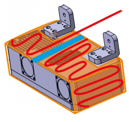
The vortex tube produces cold air, and the temperature controller inside the device controls the start and stop of the vortex tube, keeping the temperature roughly at the set value.
In scenes with intense heat radiation, the heat shield can be designed as a double layer with insulating material filled in between. Common insulating materials include fiberglass, asbestos, rock wool, silicate, aerogel felt, vacuum panels, etc.
Disadvantage: Condensation may occur on the surface of the device and the camera housing (which can be improved by adding a fan inside the enclosure).
- Bottom plate
- Rubber gasket
- Rubber gasket
- Temperature controller
- Vortex tube
- Rubber gasket
- Upper shell
3. Camera Protective Cover Design in Low-Temperature Environments
Common insulation measures include covering with a constant-temperature protective garment. The basic principle of protection is to monitor the internal temperature in real-time using a temperature sensor. When the temperature is too low, please increase the temperature by means of an electric heating plate, thereby maintaining a constant temperature in the micro-environment.
Typically, a constant-temperature protective garment consists of an insulation layer and a constant-temperature layer. During installation, it’s essential to ensure that the hook loops and the camera lens are exposed, and the heating resistance wire is smooth without any twists or distortions. The master control sensor is recommended to be placed in the mainboard position. Please perform regular cleaning and inspection of the protective garment’s surface, preferably once a week, to effectively extend its lifespan.
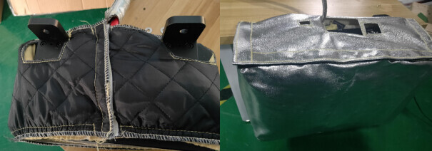
Disadvantage: It is necessary to consider situations where the camera protective garment may lead to poor heat dissipation during seasonal changes.