For latest contents, refer to docs: Check Whether the Robot Absolute Accuracy Has Declined
Context
During the project implementation and stable operation phases, there are occasional situations where the accuracy of camera extrinsic parameters meets the requirements, the point cloud viewing in Mech-Vision also complies with the picking requirements, but the picking is still inaccurate.
For example:
- The workpieces can be picked in the forward direction, but there is a deviation in the picking of backward workpieces.
- There is a deviation between the picking poses created by the drag-and-drop method and the actual picking pose.
For applications involving robot picking of workpieces, the ultimate picking error primarily originates from two main sources:
- Camera Section (including the camera itself, extrinsic calibration errors, and visual errors)
- Robot Section (including robot absolute accuracy and TCP errors)
These two sections are not entirely independent, and the latter can impact the former. Here, we will only discuss the “Robot Section.”
Robot accuracy is divided into repeatability (which can be further divided into the repeatability of a single point and the repeatability of a path) and absolute accuracy. For applications where the robot move is taught through the teach pendant, the picking accuracy is only affected by the robot repeatability. On the other hand, for applications where the picking pose comes from external inputs (such as software simulation), picking accuracy is mainly influenced by the robot’s absolute accuracy.
The following are methods for checking robot accuracy, presented in the recommended inspection sequence.
Note:
Before starting the investigation of the above issues, please ensure that all infrastructure, such as the robot base and camera mount, is securely fixed and does not experience any movement or looseness.
Step 1: re-align robot zero point
When robots are delivered from the factory, they undergo testing using instruments to set up the robot’s zero position. In this zero position, the graduation lines on each axis are generally aligned.
(Some robot suppliers also provide the encoder values of each axis when the robot is in the zero position. Unless the joint motors and encoders are separated, this value will not change. If there is not a significant deviation in the zero graduation lines, further checks can be made for consistency between the value in the teach pendant and the delivered value.)
The primary reasons for the loss of “zero position” are as follows:
- The robot encoder battery discharges, leading to the loss of encoder values.
- Incorrect zero-point calibrations.
When in the “zero position,” if the graduation lines are noticeably misaligned, the robot precision required for high-accuracy vision applications can not be achieved even through manual recalibration of the zero point. In such cases, the support of the robot manufacturer and specialized instruments (such as probes or 2D cameras) is necessary. Please consult your robot supplier.
If the problem persists after re-aligning the zero point, please proceed to the next steps.
Step 2: recalibrate TCP
In this step, recalibrating the TCP refers to calibrating the TCP used to verify robot accuracy, not the TCP for picking. The calibration methods for the TCP of some robot brands have been summarized in the community. Please refer to Robot TCP Calibration Operation Method.
If the problem persists after recalibrating the TCP, please proceed to the next steps.
First, check if the camera’s image capture and vision processing results are accurate.
If you have confirmed that both camera capture and visual processing are not problematic, then it is necessary to verify whether the robot has indeed lost its absolute accuracy. If so, the robot may need to be repaired.
Step 3: quickly assess the absolute accuracy of a robot
What is absolute accuracy?
- Absolute accuracy is the alignment between the robot in CAD systems and the physical robot.
- Understanding Robot Absolute Accuracy Webinar by KUKA - Robots & Automation on YouTube
Assessing the absolute accuracy of a robot typically requires specialized equipment such as a laser tracker, but such conditions are often not available on-site. The following summarizes several common, qualitative, and on-site operable assessment methods, listed from easy to difficult in terms of operability:
Robot pose variation assessment with fixed point
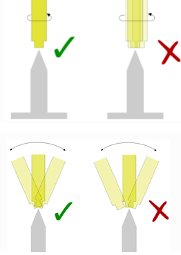
Prepare a pointed object (a pen works as well) and calibrate its TCP value at the robot end. Then, perform large-angle pose variations around the TCP in different rotation directions (Rz, Ry, Rx). Observe the fluctuation in the pointed object’s position—the smaller the positional fluctuation, the higher the robot’s absolute accuracy.
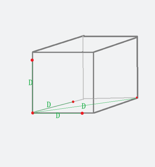
Let the robot move in straight lines, measuring distances at multiple point pairs
Select two points on each of the X, Y, Z axes and the diagonals. Read the robot’s movement distance D from the teach pendant, measure the physical distance D’ with a ruler, and compare the difference. It is recommended to perform measurements in all three directions (XYZ) and at different positions. The smaller the overall difference, the higher the robot’s absolute accuracy.
Robot arc movement, evaluating circular movement
It is necessary to have a true circle as a reference or auxiliary equipment for evaluating circularity (such as a dial indicator).
Step 4: Calibrating the TCP for Picking
If the problem persists after performing Steps 1-3, it is advisable to calibrate the TCP used during the picking process.
One common issue with the inaccurate picking TCP is that the theoretical TCP is not perfectly aligned with the actual picking TCP, resulting in a relative offset, which causes rotation errors for the gripper. A typical manifestation is the inconsistency in the relative positions of the gripper and the workpiece when picking in the ‘forward’ and ‘reverse’ directions. However, the method for calibrating the TCP for picking is dependent on the gripper design and requires a case-by-case analysis based on specific scenarios.