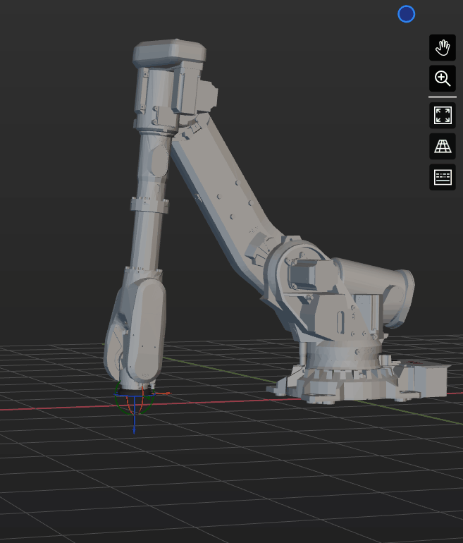
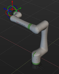
Robot Kinematics
Robot Configuration
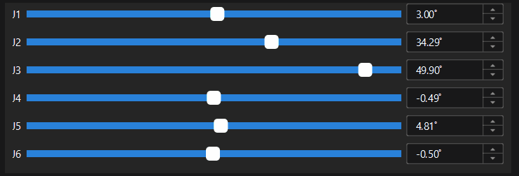
This involves using equations to establish the relationship between the robot’s flange pose and the angles of its joints. Robot configuration equations encompass parameters such as the lengths of robot links (DH parameters), joint positions (JPs) at 0°, and the rotation directions of each joint.
Different robot structures, such as six-axis spherical wrists, four-axis Scara arms, various offset wrist collaborative arms, require distinct robot configuration equations. Currently, Mech-Viz supports all common industrial robot configurations available in the market.
Forward and Inverse Kinematics
Forward Kinematics: Given the angles of each joint of the robot, these joint angles are substituted into the robot configuration equations to calculate the tool pose of the robot. Since the joint angles are fixed, the tool center point (TCP) is uniquely determined.
Inverse Kinematics: When the tool pose of the robot is known, the joint angles of each axis are calculated in reverse. Because there is only one known parameter, which is fewer than the unknowns, multiple solutions may exist. In other words, inverse kinematics for robots is not unique.

When Mech-Viz completes robot path planning and sends the planned results to the robot, if joint positions (JPs) are sent, the robot performs forward kinematics calculations, and there are no issues with multiple solutions. The robot’s motion path aligns precisely with Mech-Viz’s planned results. However, communication using TCP is still widely used in many scenarios, due to the following reasons:
- Some robots do not support receiving joint angles in certain situations.
- Robot controllers have built-in compensation algorithms, enabling higher motion accuracy when controlling using tool center points (TCP).
- Using TCP for communication facilitates secondary processing in later stages.
Axis Configuration
As shown above, TCP (tool center point) has many advantages compared to JPs (joint positions). The only drawback is the possibility of multiple solutions, which may lead to inconsistencies between the robot’s pose obtained after inverse kinematics and the one planned by Mech-Viz software, potentially causing collisions during robot motion. To avoid this issue, robot manufacturers have added axis configuration parameters in robot motion commands.
Axis configuration consists of four additional parameters. Three of them are used to specify the angle ranges for the 1st, 4th, and 6th robot axes. The fourth parameter specifies the robot pose types for the 2nd and 3rd axes. By adding boundary conditions, the multiple solutions from inverse kinematics can be filtered out. This feature will be added in future versions of Mech-Viz.
Singularities
There are three situations that can lead to robotic singularities, but in industrial settings, only one is commonly encountered: when the 4th and 6th axes of a six-axis spherical wrist robot approach coaxial alignment, especially during linear motion.
Avoiding Singularities
Singularity issues are inherent problems in six-axis spherical wrist robots, and various manufacturers have made different attempts to mitigate these problems:
-
Developing offset wrist robots: Altering the robot’s structure to avoid situations where the 4th and 6th axes become coaxial, thereby preventing singularities. Examples include UR and FANUC’s CRX series.
-
Introducing new commands in robot controllers: Incorporating new commands within the robot controller to utilize moveJ as an approximation of moveL, thus addressing singularities.
-
The Mech-Viz software reduces the robot velocity when singularities occur and attempts to plan again.

Mech-Viz’ Singularity Detection
Different manufacturers have varying methods and criteria for detecting singularies in robots, and these methods are not publicly disclosed. Mech-Viz software’s singularity detection method cannot guarantee consistent results with the manufacturer’s detection. This may lead to the following situations:
- Mech-Viz planning is successful, but the robot reports a singularity error.
- Mech-Viz planning fails with a singularity error, but the robot can follow the same path.
In future versions, the software will incorporate algorithms that approximate moveJ to moveL, mitigating singular point issues to some extent.
Robot Motion Types
Robot motion generally refers to the process of the robot’s TCP moving from point A to point B in space.
Joint Motion
Joint motion refers to the robot’s movement from point A to point B, where each axis rotates with the minimum angle and completes its rotation simultaneously. In this mode of motion, the movement of the tool center point is not linear, and it does not result in singularities.
Linear Motion
Linear motion refers to the robot’s movement from point A to point B, where the TCP remains on the line connecting points A and B. This mode of motion offers better predictability in the path, but not all movements can have feasible linear motion solutions. In other words, the robot motion might have no solution, or it might encounter singularities during the motion.
Relative Movement
Relative movement is just a specific way to describe the target waypoint. Instead of directly describing the target waypoint in space, relative movement defines the target waypoint by describing its offset relative to a reference point. Relative movement is widely used in robot motion systems due to its convenience and the ability to automatically adjust based on changes in the reference point.