Introduction
Target Reader: Solution Engineers, Layout Planning Engineers, Mechanical Design Engineers, Mechanism Design Engineers, etc.
Post Overview: This post focuses on loading housings. It elaborates in detail on common challenges encountered in the industry, such as incoming materials for housings, picking, working space, and corresponding solutions to address these challenges. This information provides significant guidance for the overall design of the solution, ensuring smooth progress through subsequent project phases.
Distinguish similar objects
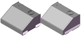
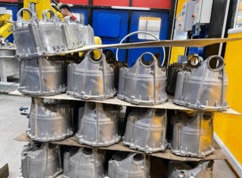
Issue: When the Mech-Eye Industrial 3D Camera distinguishes between objects that are similar in dimension, shape, and features, the result from vision recognition can be very unstable due to the environment and other factors. For example, these two fuel tanks are exactly the same in dimension and shape, as shown in the figure below. The camera distinguishes between them mainly by the features of their side walls (white part in the figure). In order to facilitate picking, the camera needs to capture images from the top, which makes the recognition result of those features very unstable.
Solution:
- When the camera setup is ETH, you can add a 2D camera at a suitable position along the robot’s unloading path. This camera is used to capture images of the surface features of the objects, and therefore the objects can be distinguished.
- When the camera setup is ETH, if the vision recognition cycle time allows, you can add a camera on the robot to capture images of the features, and therefore the objects can be distinguished.
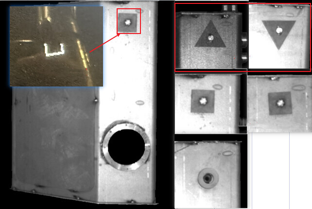
- Considering the object properties and various factors in the production process, you can add special marking blocks on the surface of the housings whether in the ETH or EIH setup. The surface you choose should be within the camera’s field of view. These special marks are used to distinguish objects and can increase the recognition success rate. (Note: The marking blocks should be consistent in dimension, style, installation position, and orientation, otherwise, the vision system will recognize the objects as different models.)
Inconsistent orientations of loading objects
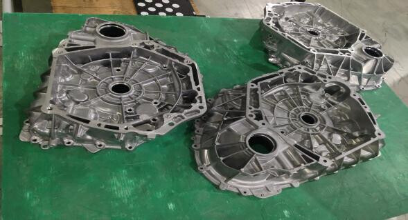
Issue: Generally, the incoming objects are placed manually in a random way or jolted during transportation, resulting in inconsistent orientations of incoming objects. There may even be objects with front side facing upwards and others with their back side. Therefore, the gripper may interfere with the adjacent objects, the bin, or the fence when it picks the target object.
Solution:
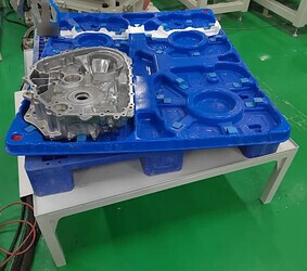
- You can add high-fraction pads or design form-fitting grooves on the partition to constrain the poses of incoming objects (as shown in the figure below), which can ensure that the poses are consistent.
- After you have completed the initial design of the gripper, you can simulate your project according to the loading poses that may occur, and adjust the gripper based on the simulation results. This can ensure that the gripper adapts to various poses.
Inconsistent pallet patterns
Issue: The arrangement of housings and partitions in the incoming stack is chaotic. The housings are placed randomly with front and back side alternatively facing upward. This can easily lead to recognition errors and also brings challenges to the applicability of the gripper.

Solution:
- Set strict criteria for the poses of incoming objects. If the pose of the incoming stack does not meet the criteria, as shown above, it should not be sent to the loading workstation.
- When designing the gripper, you need to consider whether it is suitable for picking the objects from both the front and the back.
- On the vision side, you should establish an error reporting process in advance, and notify the customer that if the objects collapse or the objects are stacked with front and back side alternatively facing upwards, manual intervention is required.
Unstable pallet patterns
Issue: The partition is thin or the support points of the objects at the bottom are too concentrated. In real practice, if the robot finishes picking at one side, the objects on the current layer may tilt towards the other side.
Solution:
- Use thick partitions and adjust the arrangement of the objects at the bottom to ensure the support points are evenly distributed.
- Change the picking sequence. For example, pick the objects from the corners to the center.
Objects out of camera’s field of view
Issue: Due to the excessively large constraint area at the loading position or the improper setting of the stop block, the incoming pallet or objects shift significantly at this position, making the objects out of the camera’s field of view. As a result, the camera cannot capture images of the objects.
Solution:
-
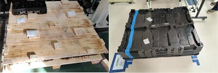
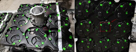
In scenarios where the objects are coming in multiple layers and bins are not used, you should take measures to secure the partition and the objects at the bottom, as shown below. The left image shows an object secured in the groove of the partition. The right image shows a circular groove at the bottom of the partition within the red box, which fits closely with the circular ring on the upper surface of the object, ensuring that the position of the object on the pallet does not change to avoid the object out of the camera’s field of view.
-
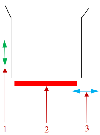
A proper stop block design should be that the pallet is positioned in one direction and constrained in the other direction. As shown in the figure below: 1. Constraint direction, 2. Positioning block, 3. Positioning direction.
Gripper interference
Issue:
- When the robot performs the picking task at a workstation, if the height of the objects at the adjacent workstation is higher than that of the current picking layer, the gripper may interfere with these objects.
- If the objects on the same layer are arranged too compactly, or the picking sequence is improper, it may lead to failure in picking or interference during the picking process.
Solution: When you are designing the project, you should simulate the project to check the picking and placing processes of the whole workstation. When necessary, you can take measures to avoid interference between the gripper and the surrounding environment during the picking process, such as constraining the height of the incoming materials, and adjusting the number of objects on a single layer and the distance between the adjacent workstations.
