Usage Scenarios
In many cases, the object to be picked does not necessarily have a unique pick point, or its geometric center is not necessarily the most suitable pick point. This may be due to the complex and diverse shapes of objects, or the surface characteristics of the object affecting the selection of pick points. Therefore, we need to employ a mapping method to map the geometric center of a single workpiece to one or more potential pick points. Such a method ensures that we have alternative picking strategies in different situations, thereby increasing the success rate of picking.
Input and Output
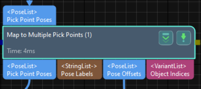
“Map to Multiple Pick Points” has one input and four outputs:
Input:
- List of geometric center points of the object (matched or computed result)
Outputs:
- List of pick points
- List of labels corresponding to pick points
- List of pose offsets
- List of object indices
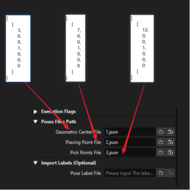
Parameter Description
-
Geometric Center File: The pose of the object’s geometric center point on the point cloud model. Used for matching as the geometric center point.
- File path: Project → Vis project name → resource → 3d_matching → point cloud template name → geo_center.json
-
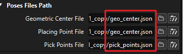
Placing Point File: Pose of the placement points for objects. The point on the model point cloud where placement occurs, with that point as the center.
- File path (same as geometric center file for guided picking-type projects): Project → Vis project name → resource → 3d_matching → point cloud template name → geo_center.json/pick_points.json/xxxx.json
-
Pick Points File: The pose of the object’s pick point on the point cloud model. The point on the model point cloud used as the center for picking.
- File path: Project → Vis project name → resource → 3d_matching → point cloud template name → pick_points.json
-
Pose Label File: Label file corresponding to the pick point.
Usage Instructions
Output 1: List of pick points
Based on the relative position relationship between the geometric center and the placing point: The initial input poses are transformed again through the transformation relationship between the placing point and the geometric center.
Output 3: List of Pose Offsets
Based on the relative position relationship between the pick point and the placing point: The position of the pick point relative to the placing point.
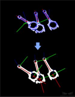
The following two figures provide simple examples to demonstrate the actual input-output transformation:

1. Placing points are the same as geometric center points
1) There exist one or multiple pick points without symmetry or the pick points are different from the geometric center:
In this case, we need to output the actual pick points, so we need to follow the “Map to Multiple Pick Points” step with a “Transform Pose”. Pay attention to the way these two steps are connected.
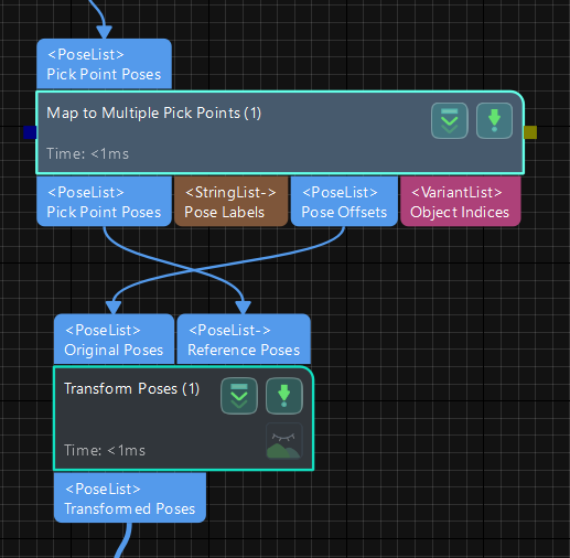
At the same time, the selection of options for “Transform Pose” needs to be as shown in the following figure:
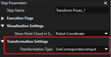
After the “Transform Pose”, the original pose undergoes a linear transformation (in the Mech-Vision software, this step is left-multiplied, with the reference poses on the left and the original poses on the right).
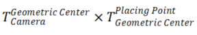
Therefore, when we need to map the geometric center point of an object to multiple pick points, we need to combine these two steps to achieve a similar effect as the formula described below, obtaining the pose of the pick point in the camera coordinate frame.

By doing so, we will ultimately obtain the desired pose(s) of one or more pick points in the camera coordinate frame.
2) There exist one or multiple pick points with symmetry or the pick points are the same as the geometric center:
In this scenario, we have two options:
- Adopt the same strategy as in the case of “There exist one or multiple pick points without symmetry or the pick points are different from the geometric center.”
- Skip using the “Transform Pose” and directly output the pose of the geometric center in the camera coordinate frame along with the offset between the geometric center and the pick points. In this case, you can add symmetry to the object in Mech-Viz. Mech-Viz will automatically adjust the offset after selecting the corresponding geometric center point, providing the final pick points.
2. Placing points are the same as pick points
In this case, the third output of the step, “Pose Offsets,” is 0, and the first output of the step represents the pose of the placing point/pick point in the camera coordinate frame. This can be directly outputted.
3. Placing points are different from both the geometric center and the pick points
In this case, since we need to use a different point (placing point) as the center for positioning when placing the workpiece, which is different from both the pick points and the geometric center, we need to set up a separate placing point file.
It’s important to note that the “Placing Point File” in the steps doesn’t refer to the position where the workpiece is placed (i.e., a specific point in the robot’s coordinate frame), but rather a point on the workpiece. Similar to the geometric center, placement is done with this point as the center.
The first output in this scenario represents the pose of the placing point in the camera coordinate frame:

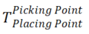
The third output represents the relative positional relationship between the pick point and the placing point:
We can send this offset along with the placing point’s pose to Mech-Viz for corresponding adjustments or process it in Mech-Vision accordingly.