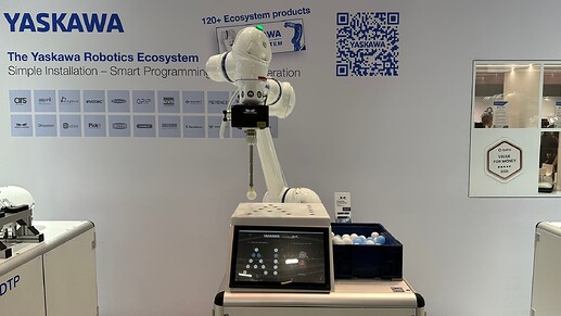
In this post we will look at the bin picking application with a focus on the custom GUI that was displayed at the YASKAWA booth at Automatica23 in Munich, Germany.
Fig. 1: Bin picking cell as seen at the trade fair
Task Description
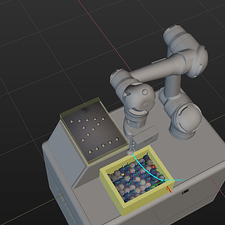
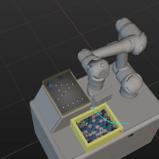
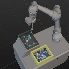
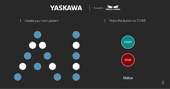
The scene consists of the robot, the bin for picking (filled with table tennis balls), and a platform to place the balls, as can be seen in Fig. 1 and Fig. 2. How the balls should be placed is specified in a Guided User Interface (GUI) that was custom-built for this application. The user chooses a pattern and presses Start. The robot then picks a ball of the desired color and places it at the next position in the pattern. If the pattern is complete or the user presses Stop and Start again, the robot takes all balls from the platform and drops them in the bin for picking, effectively resetting the scene.
Fig. 2: Simulated robot picking balls and placing them in specified pattern
Setup
- Software Version: 1.7.1
- Camera: Mech-Eye Nano V3 (SDK Version 2.1.0)
- Robot: YASKAWA HC10DTP
Mech-Vision
Workflow
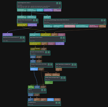
The Mech-Vision project follows the typical structure of a DL supported project:
- Camera Triggering
- Point Cloud Segmentation and Object Class Recognition with DL (Instance Segmentation)
- Model Matching
- Pose Transformation
Fig. 3: Mech-Vision overall workflow
Tips and Tricks
Model Matching
In this application, DL is used to detect the table tennis instances and their label (blue or white). The step Deep Learning Model Package Inference returns the 2D mask for each instance and its label. The model was custom trained on only ten images. In a subsequent step, Apply Masks to Point Cloud, the 2D mask is used to segment the Point Cloud into the parts of each ball. Note that instead of DL, Clustering and Color Thresholding could have also been used to achieve the segmentation.
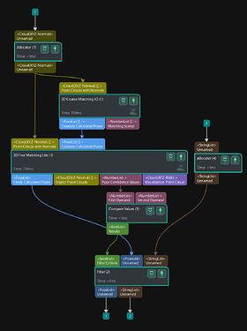
Afterwards, the typical matching procedures, 3D Coarse Matching V2, and 3D Fine Matching Lite, are used to match the model of the ball (see Fig. 4). Since each segmented point cloud only contains a single ball, the parameter Maximum Number of Detected Poses should be set to one.
Attention should be paid to setting the Confidence Threshold parameter. This value has to be set to 0 in the 3D Fine Matching Lite step, and subsequently, the Compare Value step has to be used to filter out low confidence results. The reason is that the label of the ball is already determined before the matching step. For each of the N point clouds, a matching result is returned if the confidence threshold is set to 0. Therefore, the pose list of the fine matching step has a length of N. If you were to filter out the low confidence values during the matching step, you would lose the one-to-one correspondence of the pose list and the label list. This is the reason why you need additional steps to apply the confidence threshold.
Fig. 4: Mech-Vision matching workflow
Pose Filtering
In order to pick only a ball of the correct color for the next position in the placing pattern, the step Validate Labels and Output Flags is used to filter the poses by the label, as shown in Fig. 2. To achieve this, the reference labels are set externally using an adapter. How this can be done in the adapter will be explained later in this post.
Pose Transformation
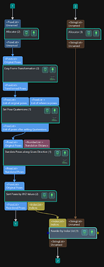
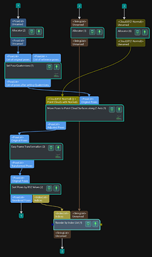
Independent of the matching result, the z-axis of the ball should point straight up. To achieve this, there are multiple possibilities, two of which are shown in Fig. 5. The orientation of the pose is set via a desired quaternion, resulting in an alignment of the object’s z-axis with the z-axis of the camera or robot frame, depending on whether the pose was transformed to the robot frame beforehand or not.
Secondly, the pose (defined at the ball’s center) has to be translated to the ball’s surface. Alternatively, the TCP (Tool Center Point) of the gripper could also be adjusted such that the TCP is not at its tip but at an offset (the ball’s radius), making the translation redundant.
Fig. 5: Two possibilities to transform the poses
Mech-Viz
In this application, the logic of Mech-Viz is partly controlled by an adapter. The adapter is a Python script that sends and receives control and status commands from Mech-Viz and can thereby be used for more complex projects. The script used for this case is shown in the next section called Adapter.
A branch_by_msg step is used to differentiate between normal operation (branch 0) and the operation that should take place once the user hits the stop button (branch 1). During normal operation, first, all balls on the platform are removed, and afterward, the balls are picked from the pick box one by one and placed on the platform.
As you may have noticed in Fig. 6, Notify steps are used. The Notify step is used to send a message to the adapter. In this case, different functions of the adapter are called when the adapter receives the message.
Once the pattern is complete (Check Completion evaluates to True), the loop is exited, and the Viz program is terminated. It will be restarted once the user defines a new pattern and presses Start.
Fig. 6: Mech-Viz overall workflow and the workflow for picking and placing
Adapter and GUI
Setup
To use an adapter (and a UI) it is necessary to define the path of the parent directory of the adapter in Mech-Center/Deployment Settings/Mech-Interface. Once you press Start Interface in Mech-Center the adapter (and the UI) are started. it is also possible to use an adapter without a UI.
The adapter directory should look like this:
- __init__.py
- adapter.py
- widget.py
Important is that the __init__ file has this structure:
import sys
import os
from Adapter.adapter import AIAdapter
from Adapter.widget import CustomGui

_adater_path = os.path.abspath(os.path.join(os.path.dirname(__file__)))
if _adater_path not in sys.path:
    sys.path.append(_adater_path)

adapter_dict = {os.path.basename(_adater_path): AIAdapter}
adapter_widget_dict={os.path.basename(_adater_path): CustomGui}
GUI
The GUI is based on a Pyside2 Widget and is created like this:
... # custom imports here
from interface.adapter import AdapterWidget

class CustomGui(AdapterWidget):
    def __init__(self):
        super().__init__()
        ... # custom code here

    def pattern_completed(self):
        ... # custom code here

    def after_set_adapter(self):
        ... # custom code here
        self.adapter.pattern_completed_signal.connect(self.pattern_completed)
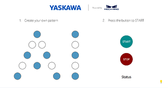
Therefore, you can develop a UI with all the possibilities that Pyside2 offers. Note that the CustomGUI class has to inherit from AdapterWidget. When the user interface in Mech-Center is started, the adapter is assigned to the UI instance. Afterwards, the method after_set_adapter is called, where you should connect signals of the adapter with the signals of the Widget. For example, in this case, whenever the signal pattern_completed_signal of the adapter is triggered (which happens once all balls are placed) the method pattern_completed defined in the widget is called. The UI developed for this application is shown in Fig. 7.
Fig. 7: Custom GUI of the application with and without dark mode
Adapter
Importing the required modules:
import logging
import json
from functools import partial

from PySide2.QtCore import Signal, QTimer

from interface.adapter import TcpServerAdapter
from interface.services import NotifyService, register_service
To receive messages from the Notify step in Mech-Viz it is necessary to define a service class:
class NotifyLogic(NotifyService):
    service_name = "Viz_Notify"

    def __init__(self, adapter):
        self.adapter = adapter

    def handle_message(self, msg):
        if msg.lower() == "next":
            self.adapter.set_current_pick_color()

        if msg.lower() == "index_increase":
            self.adapter.index += 1
            self.adapter.msg_signal.emit(logging.DEBUG, f'index_increase:{self.adapter.index}')
            self.adapter.set_current_pick_color()

        if msg.lower() == "finished":
            self.adapter.pattern_completed_signal.emit(True)
            self.adapter.index = 0
The method handle_message of this service class is called every time a Notify step in Mech-Viz is exectued. Note that in the Notify block, you have to specify the service name of the service class that receives the messages, Viz_Notify in this case.
Depending on the message (a string) a different routine will be executed.
adapter.msg_signal.emit can be used to log output to the Mech-Center console.
Finally, the control logic is defined in the AIAdapter class that inherits from the TcpServerAdapter:
class AIAdapter(TcpServerAdapter):
    robot_name = None
    pattern_completed_signal = Signal(bool)

    def __init__(self, address):
        super().__init__(address)
        try:
            self._register_service()
            logging.info('Services succesfully registered!')

        except Exception as e:
            logging.error(f"Services could not be succesfully registered! \n {e}")

        self.set_recv_size(1024)
        self.set_pattern([])  # empty init

    def set_current_pick_color(self):
        visionStepName = "SetBallColor"
        visionProjectName = "YASKAWA"
        color = str(self.pattern[self.index]) # get color

        msg = {"name": visionStepName, "values": {"strings": color}}
        self.msg_signal.emit(logging.DEBUG, "Blue" if color == '0' else "White")
        self.set_step_property(msg, visionProjectName)

    def set_branch(self, name, out_port):
        try:
            info = {"out_port": out_port, "other_info": []}
            msg = {"name": name,
                   "values": {"info": json.dumps(info)}}
            QTimer.singleShot(500, partial(self.set_task_property, msg)) # delay
            self.msg_signal.emit(logging.INFO, f"Set port {out_port} of {name}")
        except Exception as e:
            logging.exception(e)

    def set_pattern(self, pattern):
        self.pattern = pattern
        self.index = 0 # reset

    def _register_service(self):
        self.adapter_service = NotifyLogic(self)
        self.server, _ = register_service(self.hub_caller, self.adapter_service)

    def _unregister_service(self):
        if self.adapter_service:
            self.hub_caller.unregister_service(self.adapter_service.service_name)

    def close(self):
        super().close()
        self._unregister_service()
Importantly, the pattern_completed_signal has to be defined as a class variable (a PySide2 peculiarity), and the notify service has to be registered in the _register_service method.
The output port of the branch_by_msg step can be set as shown above. Note that QTimer is used to execute the function with a delay. The reason is that the branch is set immediately after the ‘start Mech-Viz’ command is sent. However, Mech-Viz does not immediately start after the command but only starts running with some small delay. Introducing a small delay ensures that the set branch command is sent after Mech-Viz is running, resolving this issue.
In order to pick only balls of a certain color, the method set_step_property is used. This method overwrites values that are set in the specified step (‘SetBallColor’) of the specified Vision project (‘YASKAWA’ here). Therefore, before the camera is triggered, the color for the next position in the pattern is set.
- This is helpful.
- This is not helpful.
