Scenario Consideration
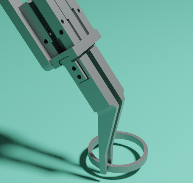
When using a general cylinder-type gripper to grip the edge of a thin metal ring workpiece, how should the gripping points be set so that the gripper can attempt to grip as much as possible?

I. Two setting methods on the Mech-Vision end
- Manual setting of multiple ring edge gripping points
As shown in the figure below: the geometric center point is labeled 0, and the ring edge gripping point is labeled 1.

This method is the easiest to understand, but the disadvantages are obvious. It requires manual modification of the quantity in the template editor. Moreover, when there are many stacked workpieces, the number of gripping points formed in the end is very large, which is not easy to view and handle.
- Use offset to set a single gripping point
As shown in the figure below: the geometric center point is labeled 0, and the ring edge gripping point is labeled 1.

This method requires the Vision software to send an offset to Viz, which is not easy to understand. We will explain how to set this method below.
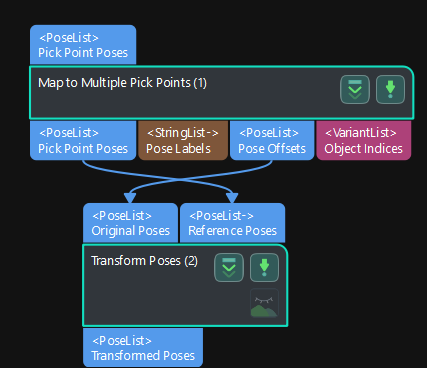
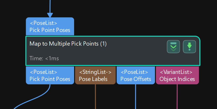
(1)Use the geometric center point when matching, and then use the “map multiple gripping points” step.

(2)Choose custom for the output step and send offsets to Viz.
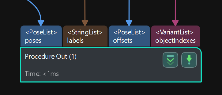
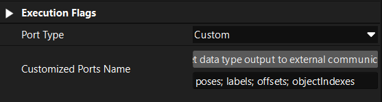
The wiring diagram is shown below.

II. Workpiece symmetry setting on the Mech-Viz end
- Under the “Workpiece” attribute, create a new workpiece named 1 (which needs to correspond to the ring edge gripping point label 1), and set the rotation symmetry around the Z-axis;
Note: Because the offset is set in Vision, the center point of the rotation symmetry here is actually the geometric center point, that is, the point where the offset is 0. Rotate around the Z-axis of the geometric center point, and then add the actual gripping point’s offset. Therefore, it can be ensured that the gripping point can still be located around the ring after the Z-axis rotation symmetry, as shown in the schematic diagram below.

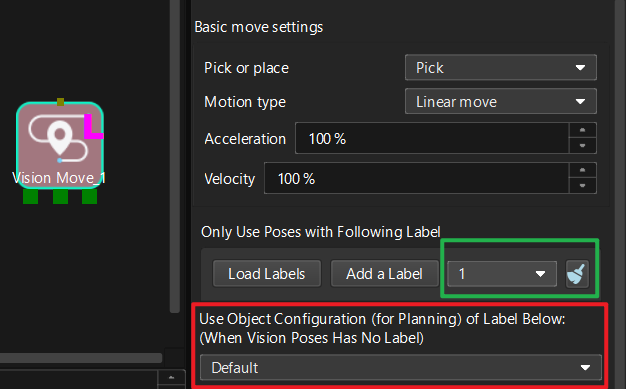
- The “visual_move” selects the corresponding ring edge gripping point label 1 (inside the green box). When the vision pose has no label, it will choose to use the workpiece symmetry parameters below (inside the red box).
III. Mech-Viz simulation gripping verification
- First, we cancel the workpiece symmetry. At this time, it can be found that the gripping point collides with the material frame, making it impossible to grip.
- After setting the symmetry parameters of Vision and Viz according to the above, simulate the plan again, and it can be found that there is an additional successfully planned gripping point “out of thin air”, and the offset setting is successful.

IV. Reference Program
The following are the reference projects of Vision and Viz. If you are not clear, please download the project for testing. The software version is 1.7.2.
Ring_Project.7z