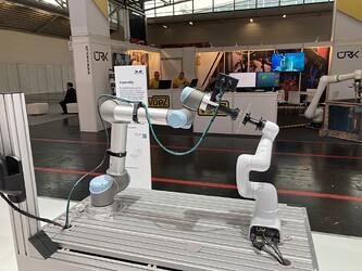
In this post we will look at the assembly application that was displayed at Automatica23 in Munich, Germany.
Fig. 1: Assembly cell as seen at the trade fair
Task Description
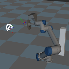
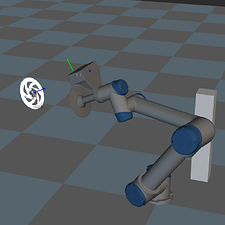
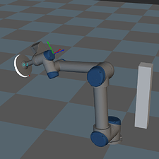
A DENSO robot randomly positions the brake disc within the scene. The position is constrained in such a way that the brake disc remains at least partially visible from the UR’s initial camera capture position. Once the brake disc is located, the UR moves to ‘mount’ the disc hub and the brake disc. To achieve higher accuracy, the UR performs an intermediate move, relocating the camera 300mm above the brake disc to recapture the brake disc’s pose. The process is illustrated in Fig. 2.
Fig. 2: Two step approach of the UR mounting the disc hub onto the brake disc
Setup
- Software Version: 1.7.1
- Camera: Mech-Eye Nano V4 (SDK Version 2.1.0)
- Robot: UR-5 (and DENSO COBOTTA holding the brake disc)
Mech-Vision
Workflow
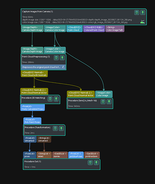
The Mech-Vision project follows the typical structure:
- Camera Triggering
- Point Cloud Generation
- Model Matching
- Pose Transformation
Fig. 3: Mech-Vision overall workflow
The runtime of the Mech-Vision project was between 1.5 and 1.8 seconds, including the camera trigger (Intel Core i7-8700). It is important to note that the runtime is dependent on the hardware used. An IPC (Industrial PC) with higher performance capabilities can achieve a lower runtime.
Tips and Tricks
Camera Triggering
Since the 2D image is not used for locating the disc brake, the 2D exposure time can be set to a minimum (1 ms), achieving a low camera capture time. However, this was not done for better visualization of the point cloud in Mech-Viz for visitors of the trade fair.
Model Matching
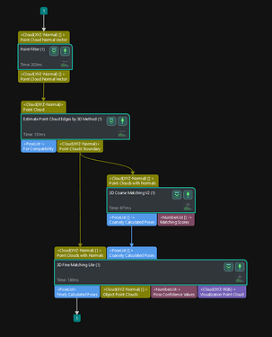
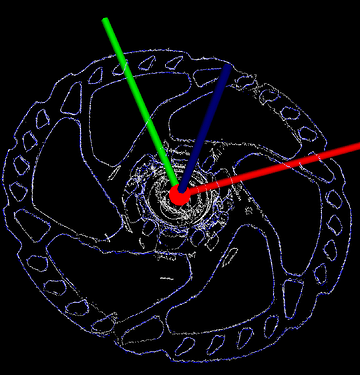
For objects with flat surfaces, such as the brake disc, Edge Matching should be used. Due to the brake disc manufacturer not releasing a CAD model, it is necessary to generate the matching model through a camera capture. When generating a matching model this way, it is advisable to remove as much noise as possible from the point cloud to achieve better matching results. Specifically, the uneven area around the brake disc center generates many edges that are not relevant for matching and, therefore, were removed from the matching model. The used matching model (visualized in blue) and the edge point cloud can be seen in Fig. 4.
To achieve highly accurate matching results while keeping the runtime low the Expected Point Count of Sampled Model in 3D Coarse Matching V2 is set to 600, and the Operation approach in 3D Fine Matching Lite is set to High accuracy.
Fig. 4: Mech-Vision workflow for edge matching and an examplary matching result
Pose Transformation
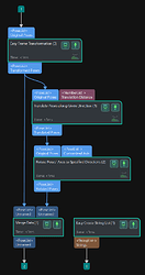
When finding the brake disc, the robot follows a two-step approach: First, it locates the brake disc and repositions the camera 300mm above it. Then, it captures another image from the optimal working distance of the camera to accurately determine the pose of the brake disc.
To achieve this, a second pose is generated by translating the initial pose 300mm along the object’s z-axis, see Fig. 5. Subsequently, the x-axis of the pose is rotated to minimize the angle with respect to the world z-axis. The purpose of this rotation is to orient the camera horizontally for the subsequent image capture which only has aesthetic reasons. If this is not desired, one could also simply use a 300mm relative move in Mech-Viz.
Fig. 5: Mech-Vision workflow for the pose transformation
Mech-Viz
Workflow
The UR robot waits for the DENSO robot, which is holding the brake disc, to complete its movement. Once the DENSO robot reaches a static state, it signals the UR robot through a DI/DO signal to indicate that it can start. When locating the brake disc in the scene, it may be partially obstructed from view due to the camera’s field of view (FOV), see Fig. 2. To ensure high accuracy in the assembly process, the UR robot repositions the camera 300mm above the brake disc and re-locates the brake disc using the now re-captured complete point cloud. The UR robot then proceeds to ‘mount’ the disc hub onto the brake disc by inserting the pins of the disc hub into the brake disc. After the assembly is completed, the robot retracts to the initial position and signals the DENSO robot via DI/DO that it finished its task and is ready for the DENSO robot to move the brake disc to a new position.
Fig. 6: Mech-Viz overall workflow
Tips and Tricks
To reposition the camera directly above the brake disc, two TCPs (Tool Center Points) are utilized: one for the camera and another for the tool. Before relocating the brake disc, the TCP is changed to the camera position. Before the assembly process, the TCP is then switched back to the tool position.
It is important to note that accurate measurement of the TCP of the tool is crucial for achieving high precision in tasks like this.
In addition to using two TCPs, two visual_moves are also utilized. In the visual_moves, the parameter Only Use Poses with Following Label is employed to filter out the correct pose for each respective step.
- This is helpful.
- This is not helpful.
