In this post we will look at the Bin Picking application that was displayed at Automatica23 in Munich, Germany.
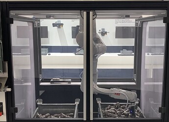
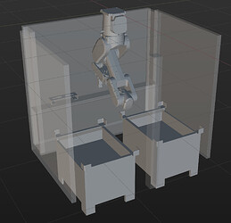
Fig. 1: Real and simulated workcell (some collision structures are set to hidden for better visibility)
Task Description
The scene consists of an intermediate storage and two bins: one for picking shafts and one for dropping the picked shafts. The robot picks a shaft from the picking bin and places it at position one. It then proceeds to pick another shaft and places it at position two. Subsequently, the robot retrieves both shafts and deposits them into the other bin. When the robot can no longer pick a shaft from the picking bin, the roles of the bins are reversed, and the picking bin becomes the placing bin, and vice versa. The routine then continues as before.
Setup
- Software Version: 1.7.1
- Camera: 2x Mech-Eye Pro M V4 (SDK Version 2.1.0)
- Robot: ABB IRB 1300-7/1.4 (same as ABB IRB 1300-12/1.4 except for maximum workload
- Gripper: Magnet Gripper
Additional prerequisites:
The robot is mounted to the ceiling which requires to change the Gravity Beta paramter in ABB’s Robot Studio to 180°. This ensures that the gravity compensation and functions, such as collision detection, work correctly.
Mech-Vision
Workflow
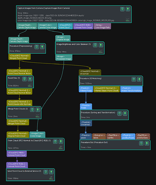
The Mech-Vision project follows the typical structure of a bin picking solution:
- Camera Triggering
- Point Cloud Generation
- Model Matching
- Pose Transformation and Sorting
Fig. 2: Mech-Vision overall workflow
The total runtime of the Mech-Vision project, including triggering the camera and matching the shafts into the scene, is around 1.3-2 seconds, depending on the amount of shafts in the bin (Intel Core i7-10700). Note that the used hardware also influences the runtime. The runtime of procedures in Mech-Vision represents the sum of the steps contained in the procedure. However, since some steps run in parallel, the shown runtime in Mech-Vision does not represent the true runtime of the procedure. The true runtime of the Mech-Vision project can be seen in Mech-Center.
Tips and Tricks
Camera Triggering
Since the 2D image is not used for locating the shafts, the 2D exposure time was set to a minimum. The image is artificially enlightened by using the step Image Brightness and Color Balancer in order to still have a good visualization of the scene. If you do not need the 2D image at all, then you can set the 2D exposure time to a minimum (1 ms) and omit any steps related to transforming the 2D image. This ensures that the highest possible cycle time is achieved as no time is spent on unnecessary image processing.
Point Cloud Generation
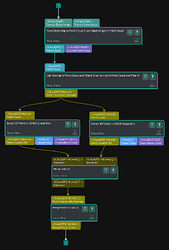
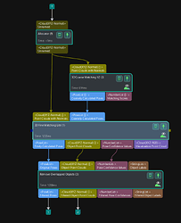
In this case, the bin has an overhanging upper edge. In order to remove the bin as well as possible from the point cloud, two 3D ROIs are used - one covering the area below the edges and one covering the area above the edges (see Fig. 3). Reducing the point cloud to only the shafts serves multiple purposes: it reduces processing time as fewer points exist (less data) and decreases the likelihood of mismatch as only the relevant points are kept (there is no accidental match with the bin, for example, if the bin had a similar surface shape as the shaft).
Fig. 3: Mech-Vision workflow for point cloud preprocessing
Model Matching
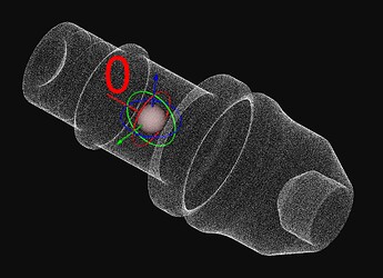
The workobject, the shaft, is rotationally symmetrical. Therefore, only at most half of the points are visible at a time (the backside of the shaft is not captured by the camera). The matching confidence is roughly calculated as the number of model points where a scene point exists within the search radius, divided by the total number of model points. To achieve a meaningful confidence value in this case, there are two options: only use the visible side of the matching model (cut the model in half along the symmetry axis and only use one side) or Only Consider Visible Surface of Model. Both approaches yield the same result in this case.
Another important setting is the Maximum Number of Detected Poses in each Point Cloud. Since we directly use the complete point cloud as input to the matching steps, the parameter should be set high enough to capture a complete layer of shafts in the bin (50 in this case). If you would first segment the point cloud by Instance Segmentation (Deep Learning) and then use the list of segmented point clouds as the base for matching, you should set the parameter only to one since each segmented point cloud only contains a single object.
Overlapping objects are filtered out after the matching. When providing Pose Confidence Values as input to the Remove Overlapped Objects step, these values will be used to determine which object to keep: if two objects overlap, the one with the higher pose confidence value will be kept. The pose confidence value of the previous matching step roughly represents the number of visible points: if the object is fully visible, many points of the model will have a corresponding point pair in the scene, and the confidence will be relatively high. If some part of the object is hidden below another object, then the confidence will be relatively low. Therefore, the confidence score is usually a good indicator of which object should be kept.
Fig. 4: Mech-Vision workflow for model matching and the matching model
Pose Transformation and Sorting
A meaningful sorting order of the objects is important for increasing the likelihood of a successful pick and reducing the cycle time. If the robot were to pick a shaft that is below another shaft, the picked shaft might fall out of the gripper while being lifted.
In addition, Mech-Viz plans to pick the shafts in the order provided by the pose list. Once a pickable shaft is found, the planning stops. Partly hidden shafts are less likely to be pickable since the gripper would collide with a shaft above. This is why well-visible shafts (likely to be well pickable) should be at the start of the list, as this reduces planning time.
A meaningful sorting order should, therefore, prioritize centered shafts of the top layer - centered because the edge overhang of the bin increases the likelihood of the shaft being dropped while being lifted. To achieve this, the poses of the shafts are sorted in a weighted manner based on the height (z-axis) of the shaft in the bin, the distance to the bin center, and the angle of the shaft’s z-axis to the robot reference frame’s z-axis, using the weight factors 3-2-1.
Mech-Viz
Workflow
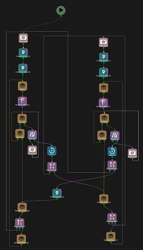
The robot picks a shaft from the picking bin and places it in the intermediate storage. It then proceeds to pick a second shaft and places it as well. Subsequently, the robot retrieves both shafts and deposits them into the other bin. When the robot can no longer pick a shaft from the picking bin, the roles of the bins are reversed, and the picking bin becomes the placing bin, and vice versa. The routine then continues as before. The branches for picking out of the two bins are identical (see Fig. 5) except for different intermediate waypoints due to the different positions of the bins.
Fig. 5: Mech-Viz overall workflow
Tips and Tricks
Keeping Track of the Program State
If the robot is not able to pick a shaft anymore, it is supposed to remove the temporarily placed shafts in the intermediate storage. In order to keep track of whether the robot has to remove one, two, or no shafts, a tag is used to represent the state (Tag=1: No shaft, Tag=2: one shaft, Tag=3: two shafts). As shown in Fig. 5, if no shaft was picked, the program changes the bin to pick from (out port 0 of the branch by tag), while the program instructs the robot to drop one or two shafts in the bin from which it just picked the shafts. Note that Tag=1 will activate out port 0 of the branch_by_tag step, Tag=2 activates out port 1, and so on.
Pick Trajectory
To succesfully pick shafts with a high probability without the shaft being stripped off at the overhanging upper edge the planned trajectory follows this scheme:
- Move above the bin.
- Move 50mm above the shaft along the z-axis of the shaft (waypoint type=Tool).
- Pick the shaft.
- Lift the shaft 50mm towards a point 1m above the bin’s center (waypoint type=Ref Point).
- Move above the bin.
Fig. 6: Mech-Viz workflow for picking
Step number 4 is particularly crucial to prevent the shaft from being stripped off at the edge of the bin. Moving above the bin before and after the pick ensures that all poses can be reached without colliding with the walls of the bin.
Point Cloud Collision
As you may have noticed, the point cloud collision detection is disabled for the last two millimeters around the visual_move point. If point cloud collision is activated, the program will only pick shafts where no point cloud collision between the robot, including the gripper, and the point cloud is detected. However, if the point cloud is noisy, this may result in shafts not being picked due to falsely claimed point cloud collision. To address this, inserting additional move steps for a small distance around the visual_move and disabling collision detection for these steps can be helpful in avoiding such issues. Additionally, it is advisable to apply a filter to the point cloud in Mech-Vision before it is sent to Mech-Viz (refer to Fig. 2).
- This is helpful.
- This is not helpful.
