0. The Composition of Error For Picking
- For a typical 3D-guided robot picking project, the whole process consists of the following steps and the corresponding errors:
(1) The 3D Vision System locates the workpieces - Vision Error
(2) The Mech-Mind Vision System transforms the poses of the workpieces from the camera reference frame to the robot reference frame - Pose Transformation Error
(3) The robot drives the gripper to pick the workpieces - TCP Error
1. Vision Error/Accuracy
-
This section describes the accuracy of different cameras and how the accuracy is calculated.
-
A. Technical Specification
The error/accuracy specifications of the Mech-Eye cameras are shown in the following figure, which can also be found in https://www.mech-mind.com/product/mech-eye-industrial-3d-camera.html.
-
B. Accuracy/Error Test Method
For both CNC and the Vision System, a ball bar is a standard tool for calibration and the accuracy test of the equipment. Let’s take PRO S camera as an example.**Test Method:** Place the ball bar in several different positions. Capture 40 images of the ball bar at each position and calculate the average value of the measurements. **Luminance:** Uniform & Indoor **Temperature:** Around 25°C With this method, an accuracy of 0.1 mm@1m was obtained. -
C. Error in the actual industrial site
Compared to the laboratory environment, the actual industrial site usually involves the following errors.
Environment Light & Reflection
Non-uniform lighting or sunlight interference will affect the quality of images, so a dark room is the best environment for 3D image capture.
Mech-Mind Camera LSR L perform well in the sunlight environment with high ambient light resistance.
Dust
Dust is one of the primary reasons for point cloud noise.

2. Pose Transformation Error
- Pose transformation error consists of robot error and calibration error.
- Robot Error
This type of error depends on robot. Generally, industry robots offer higher accuracy than collaborative robots, and robots in smaller size perform better than those in larger size. - Calibration Error
Calibration for Mech-Mind System means calculating the relative poses from the camera reference frame to the robot reference frame. Details for the whole process can be accessed in https://docs.mech-mind.net/en/suite-software-manual/1.7.4/vision-calibration/calibration.html.
A robot captures images of the calibration board with different poses, and the Vision System calculates the relative poses. 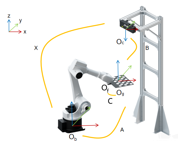
Since the pose of the calibration board is captured by the camera, the calibration error is also related to the camera’s error.
(1) Different cameras can encounter different transformation errors or accuracy problems.
(2) The center of the camera’s FOV is always the best area for calibration, while the edges and corners of the camera’s FOV often witness slight distortion.
3. TCP Error
- For most situations, the TCP error is around 0.3-0.6 mm, and can be ignored for most picking or depalletizing projects.
- For assembly or orther projects requiring high accuracy, this error can also be eliminated by the pick point teaching, which is introduced in https://docs.mech-mind.net/en/suite-software-manual/latest/vision-tools/add-pick-point-by-teaching.html.