Could anyone explain to me when (if ever) Mech-Viz will remove a tool from a model or change to a default one?
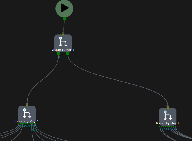
My hope is to call a Mech-Viz project shown below with 3 branches. The first branch goes to either a function branch or tool change branch. I would like to only call tool change branches when we change the tools, but don’t want to accidentally end up in situations where Mech-Viz removes one or defaults to an incorrect one.
So the process flow would be:
- Start-Viz + Set_branch calls to have Mech-Viz set Tool 1
- Run dozens of other Start-Viz + set_branch calls for functions (branches that are calling Mech-Vision programs for pick/place pose identification)
- Run another Start-Viz + Set_branch calls to have Mech-Viz set Tool 2
Is there any issues with this or reasons it might not work? (For example if I do a Start-Viz call, but don’t set a tool in the branch flow, will it retain the previous tool that was selected in the previous Start-Viz call?
Hi,Peter. There is no issues to run the project as the process flow you described.
If you have specific problems, please ask me again.
Thank you, does this also work with workobjects? It looks like during simulating held workobjects they disappear when starting Mech-Viz subsequent times.
Also, I am trying to use workobject collision detection using the geometric solid style. How do I define the point which should align with the TCP? Mech-Viz is forcing it to the centroid of the geometric solid. Even when I use the block, “Update Held Workobject” to update the pose, it offsets the robot instead of offsetting the workobject.
Thank you Haochen.
So how would I setup the custom models? I followed the directions in the Collisions document (linked at the end) but couldn’t figure out how to create the .binvox file. My colleagues are not able to export that format from Solidworks either, does Mech-Mind have a method of generating this file? I tried the .obj and .stl files but those didn’t seem to work.
https://docs.mech-mind.net/en/suite-software-manual/1.7.4/viz-simulating-running/collisions.html
Hi, Peter, sorry for the late response.
You can use this conversion tool to convert the .stl file to the .binvox file: Binvox converting script.
More information for the binvox program, please see binvox 3D mesh voxelizer, keywords: voxelization, voxelisation, 3D model.
- Conversion steps:
- Place the .stl file into the input_files directory.
- If geocenter conversion is required, you can place the corresponding .json file in the input_files directory, which will be processed together.
- Double-click the transform.py file or run python transform.py in the command line.
- Follow the prompts to input your desired resolution (commonly between 1~3 mm).
- View the model before and after conversion (remember to close the window after viewing), and wait for the .binvox file conversion to complete (this may take several seconds).
- The output files will be placed in the output_files directory.