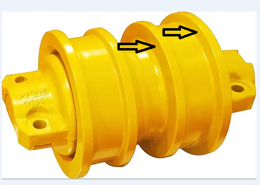
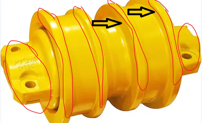
In my previous project, we encounter a struggle in 3D matching process. We use eye to hand camera setup. When we do multiple capture the result can be varied by 10 mm. Its because an error in the 3D matching we guess. Because the apearance of the surface of the part is different based on it’s position (in 2d image row x column) due to camera point of view. And the workpiece has shiny surface as well. We need an advice on how can we improve the accuracy? Should we use 3D point cloud stitching for this aplication?
Hi, could you provide more information based on the followings so that we can have further investigation on your issue:
Which camera model you were using ;
The dimension of your workpiece;
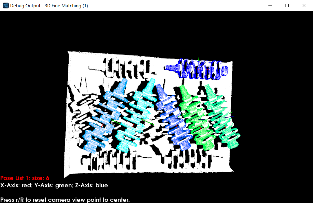
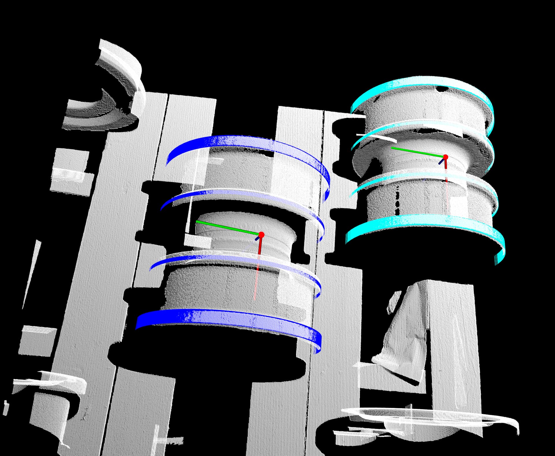
Can you show us the matching output you got;
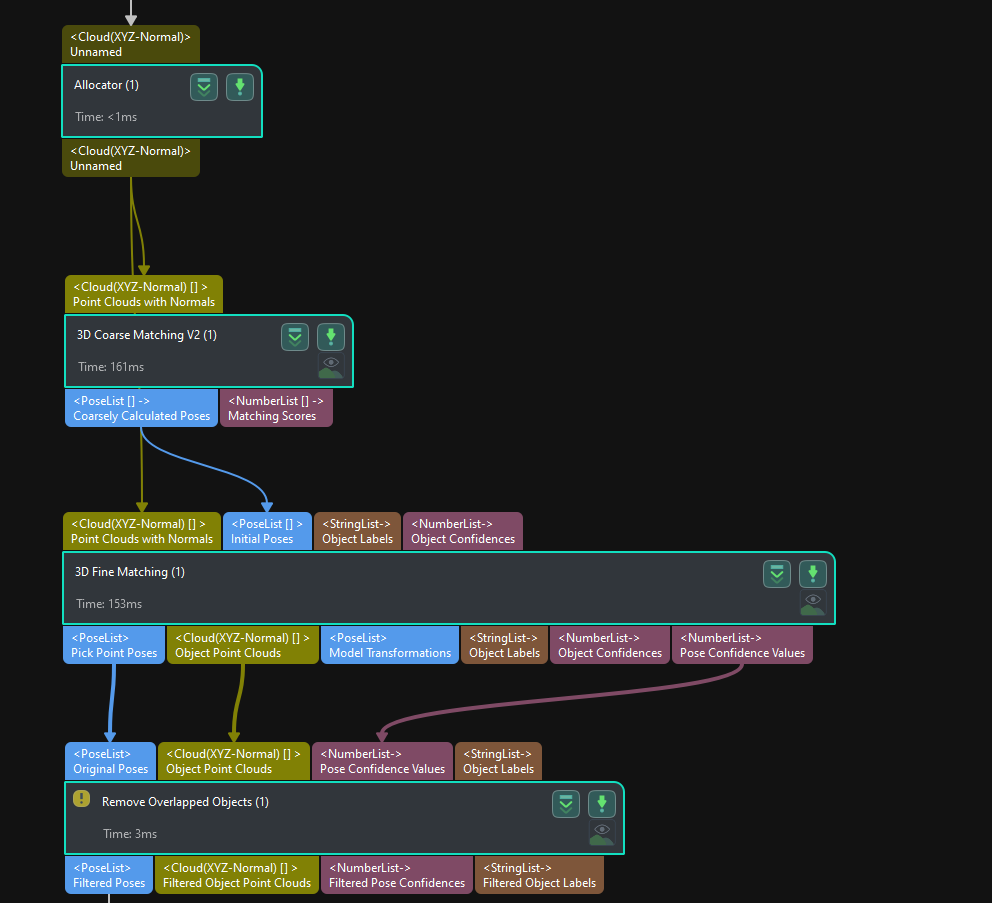
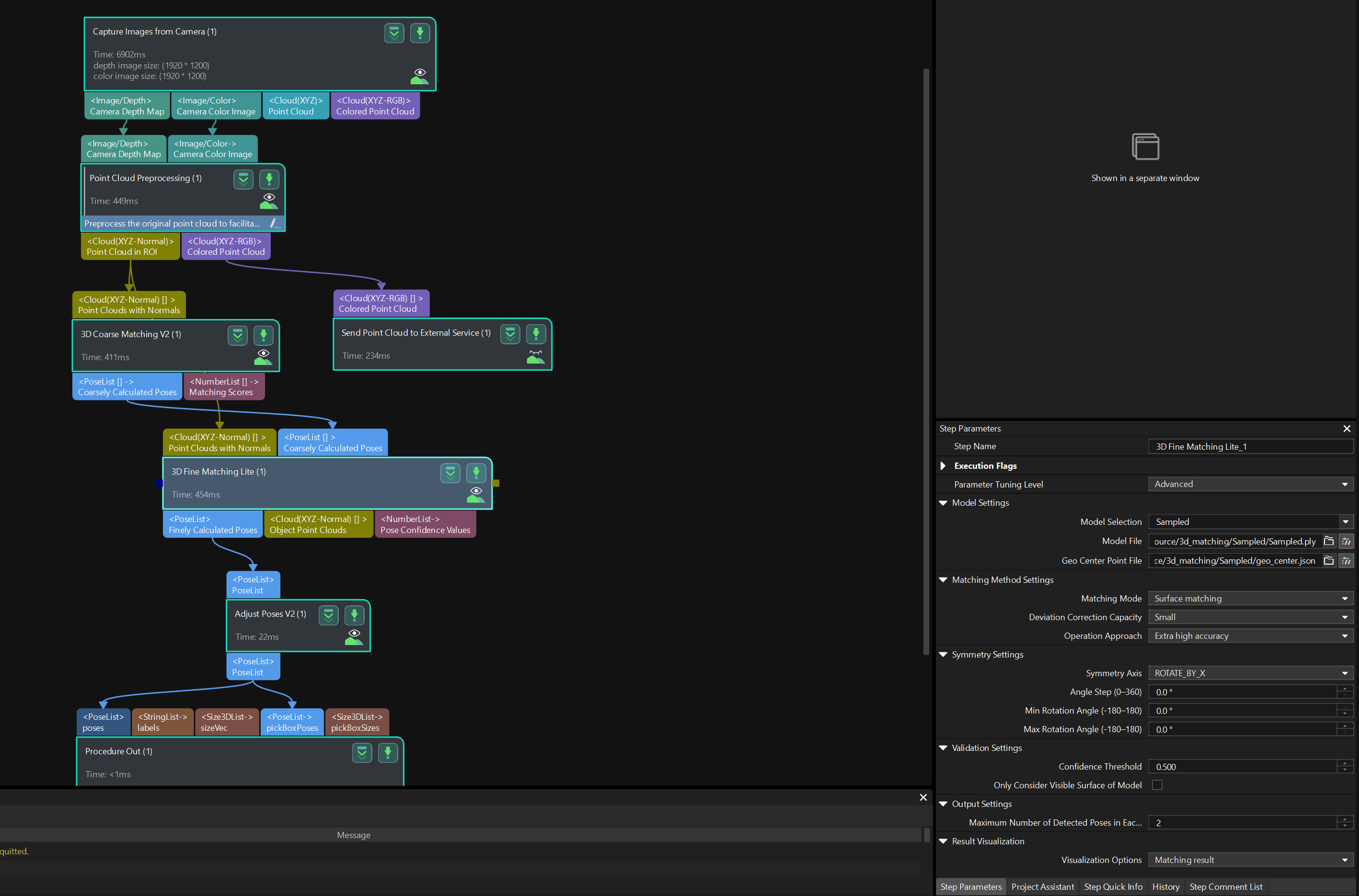
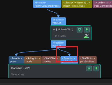
Please check if there’s any problem with your matching process in Mech-Vision, please refer to 3D Matching documentation for details, and here’re some screenshot examples:
3D Matching procedure:
Hi, I’d like to make a supplemental explanation regarding “point cloud stitching.” If a single camera can capture the entire point cloud of the workpiece, then point cloud stitching is not necessary.
Thank you for the reply. Actually we are using another camera brand in our previous project and for now we have the exact same aplication for the new upcoming project. We want to know is that enough with curent point cloud to do an accurate 3D matching or is there something shoud be improved in the setup or procedure side.
Some of the data :
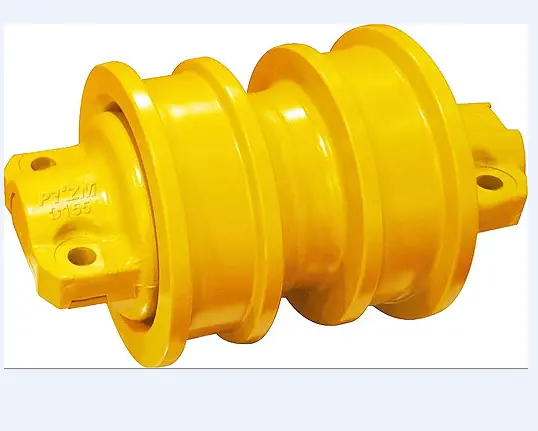
Work Piece dimension ;
diameter ; 290 mm
legth ; 330 mm
camera VoF ; 1299 x 1223 @ 1448, and
3258 x 2843 @ 3448
the distance from the camera to the workpiece is 2089 mm
the workpiece is in 3x3 grid with a gap around 100 mm each piece.
some of the point cloud missing due to camera point of view i mention before is in this area ; (because the part is not always in the center of camera FoV
Hallo!
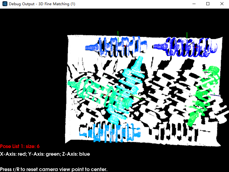
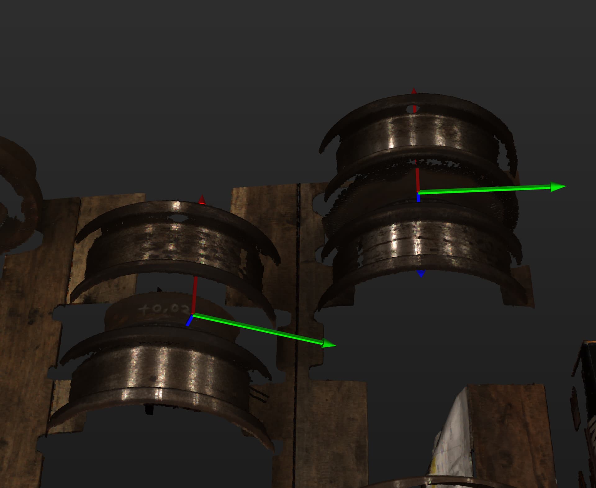
We have tried to do 3D matching with this method. The setup is Mech Mind Pro-M and the distance of the camera to the workpiece is about 1,4 m. This is the result:
When we run the program multiple time, the pick point orientation moves along workpiece center axis. Can we make pick point orientation (z axis) always vertical and (x axis) always pointing forward? what step/program tools we should looking at?
Hi,
For this case, you can set the pick point at the center of the workpiece. This ensures that when the matching result rotates along the workpiece center axis, the position of the pick point remains constant. Then, you can use the “Rotate Poses’ Axes to Specified Directions” function to orient the Z-axis upwards. Finally, use “Translate Poses along Given Direction” to move the pick point along the Z-direction by the desired radius distance.