Intro
To provide camera users with a clearer understanding of the results of the intrinsic parameter check and the extrinsic parameter files, we provide the following detailed explanation.
Intrinsic paramter Interpretation (in Mech-Eye SDK)
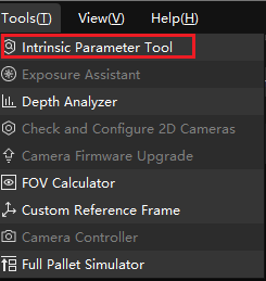
Location
Tools → Intrinsic Parameter Tool → Check intrinsic parameters

Note: For Laser L Enhanced cameras, When inspecting intrinsic parameters using Mech-Eye Viewer, please uncheck “3D Downsampling.”
Result interpretation
Result
As shown in the following figure, the results display scalar differences, vector differences, average relative position error, and average alignment error.
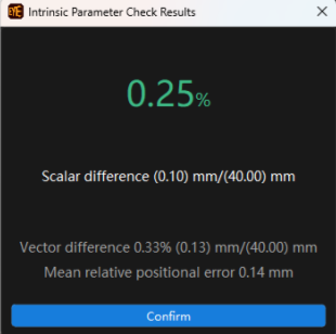
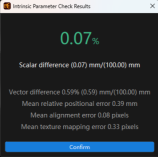
These four types of errors are the main explanatory indicators.
- On the left side are the results of the monocular camera intrinsic parameter check. On the right side are the results of the stereo camera intrinsic parameter check.
- It involves four parameters: scalar difference, vector difference, mean relative position error, and mean alignment error.
Result interpretation
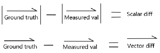
In the image below:
- Ground truth of distance
- Measured value of distance
- The magnitude of the vector represents the vector difference
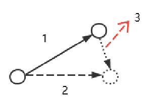
Note: The circles in the diagram represent the circles on the calibration board.
Scalar difference: It measures the difference between the measured distance and the true distance, specifically the difference between the centers of two circles on the calibration board. A scalar difference can indicate a certain level of absolute error, typically expressed as a percentage.
Vector difference: In space, the vector difference between two points can be expressed in vector form, as shown in the figure. The magnitude of the resulting vector difference represents the numerical value of the vector difference, measured in millimeters.
Mean relative position error: In the calibration board, there are multiple absolute position points denoted as the lowercase letter n. In actual measurements, we obtain several measured points, represented by the uppercase letter N. By fitting large N and small n, the average value of multiple position deviations is obtained, measured in millimeters.
Mean alignment error: Refers to the epipolar constraint error of the stereo camera, commonly understood as the relative positional relationship between the two 2D cameras of the stereo camera.
It is characterized by calculating the distance from each circle’s center coordinates on the right camera to the corresponding epipolar line on the left camera. This error reflects the difference between the actual relative pose of the left and right cameras and the theoretical value in terms of pixel disparity in the image, measured in pixels.
Note: Mean alignment error only exists in binocular structured light cameras. Monocular cameras and UHP cameras do not have mean alignment errors.
Extrinsic parameter file interpretation (in Mech-Vision)
The format of extrinsic parameters is shown in the following figure, which includes the following five key elements:
- Images captured with extrinsic parameters
- Calibration board parameters
- Extrinsic calibration configuration parameters
- Extrinsic parameter file
- Intrinsic parameter file
The specific naming form and included files for the extrinsic parameters are shown in the figure below.
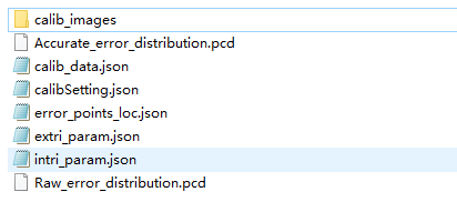
Interpretation of extrinsic parameter file
Extrinsic parameter file means the extri_param.json file. Its various sections are illustrated in the following diagram to explain their meanings.
In the screenshot below:
- Extrinsic parameters for reference frame transformation
- Compensation parameter matrix
- Camera resolution
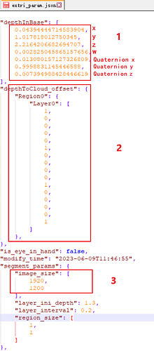
depthInBase
- The extrinsic matrix, depthInDestCoord, is used to represent the hand-eye relationship. In the case of EIH, it denotes the coordinates of the camera in the flange coordinate system, while in the case of ETH, it represents the coordinates of the camera in the robotic arm base coordinate system.
depthToCloud_offset (Compensation Parameter Matrix)
- Used to compensate for the overall accuracy deficiency in the camera system. The regions such as #Region0, and #Layer0 respectively represent partitions in the plane direction and vertical direction. Offsets will be applied to compensate for each partition.
image_size
- Resolution size of 2D images
layer_in_depth & layer_interval
- Distance between adjacent layers & Size of each plane region.
Interpretation of intrinsic parameter file
The intrinsic parameter file refers to the intri_param_json file, and the meanings of its various sections are as follows:
In the screenshot below:
- Distortion coefficients (if it’s 0, it means default distortion removal)
- Camera intrinsic parameters
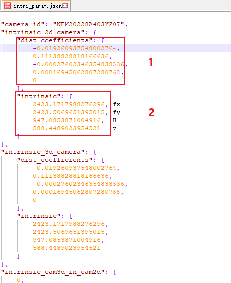
intrinsic_2d_camera & intrinsic_3d_camera
The 3D camera is used to capture stripe patterns, obtain depth information, and generate point clouds. The 2D camera is used to capture color images for deep learning or other point cloud color processing.
In Mech-Vision, camera images are categorized into three types: depth, infrared, and color. The relationship with these two parameters is as follows.
dist_coefficients
Camera distortion coefficients.
- Distortion correction is not applied to external camera images before entering Mech-Vision. RectifyImage is required for use.
- Currently, in MechEye::postprocess:
- For rectifyImage, 2D parameters are used for color, and 3D parameters are used for IR/depth.
Intrinsic
Intrinsic parameter data
- Used for conversion calculations between 2D/3D points after correcting the distortions. (fx, fy, u, v)
intrinsic_cam3d_in_cam2d
- The position of the 3D camera within the 2D camera; this value is not an identity matrix when an external camera is present.
- It is used when converting coordinate points from the color image to the depth map reference frame, such as:
- When generating a color point cloud with an external camera.
- When transforming points/coordinates from the color image to the depth map reference frame or the camera reference frame.
intrinsic_cam3d_pose_in_main
- Pose of the main camera of the 3D camera during calibration. Only for UHP cameras under secondary camera mode and projector mode, it is not represented as a unit matrix.
- This value is used when converting point clouds/poses between the camera reference frame and the robotic arm reference frame.
Obtaining intrinsic parameter file
- For the majority of cameras, the intrinsic parameter file can be directly obtained from the camera.
- Exception:
- Regular 2D color cameras: Use the Mech-Vision intrinsic calibration process to obtain the intrinsic parameter file.
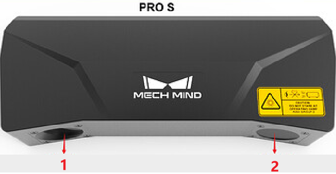
Regular 3D cameras (NANO / PRO S / PRO M)
- intrinsic_2d_camera is the same as intrinsic_3d_camera.
- intrinsic_cam3d_in_cam2d and intrinsic_cam3d_pose_in_main are identity matrices.
In the image below, 1 is the main camera and 2 is the projector.
Depth map downsamplable camera (Laser L Enhanced / Pro L Enhanced)
- intrinsic_2d_camera is different from intrinsic_3d_camera.
- intrinsic_cam3d_in_cam2d varies based on the camera configuration:
- For Laser L Enhanced, it is not an identity matrix.
- For Pro L Enhanced, it is an identity matrix.
- intrinsic_cam3d_pose_in_main is an identity matrix.
In the image below, 1 is the secondary camera, 2 is the laser projector, and 3 is the main camera.

UHP camera (default in Cam1 mode)
-
Primary camera mode (Cam1 mode)
- intrinsic_2d_camera is the same as intrinsic_3d_camera; both are in ① for 2D/3D.
- intrinsic_cam3d_in_cam2d is an identity matrix.
- intrinsic_cam3d_pose_in_main is an identity matrix.
-
Merge mode
- intrinsic_2d_camera and intrinsic_3d_camera are different; 2D is in ①, and 3D is in ②.
- intrinsic_cam3d_in_cam2d is not an identity matrix.
- intrinsic_cam3d_pose_in_main is not an identity matrix.
-
Secondary camera mode (Cam 2 Mode)
- intrinsic_2d_camera is the same as intrinsic_3d_camera; both are in ③ for 2D/3D.
- intrinsic_cam3d_in_cam2d is an identity matrix.
- intrinsic_cam3d_pose_in_main is not an identity matrix.
-
Of the UHP camera (dual-monocular) in the image below, 1 is the secondary camera, 2 is the projector, and 3 is the main camera.

Regular 2D color cameras
- intrinsic_2d_camera has a value.
- intrinsic_3d_camera is empty or the same as intrinsic_2d_camera.
- intrinsic_cam3d_in_cam2d and intrinsic_cam3d_pose_in_main are identity matrices.