Introduction
With the same set of joint position parameters, the robot in Mech-Viz may exhibit a discrepancy in joint orientations compared to the real robot, and the TCP values of the robots may also vary. When the TCP values are close to each other, the robot pose in Mech-Viz is not consistent with the actual robot pose but appears to be mirror-symmetric. The table below shows a set of robot TCP values in a specific case, wherein some TCP values correspond but joint orientations are opposite.
| X | Y | Z | RX | RY | RZ | |
|---|---|---|---|---|---|---|
| Robot TCP in Mech-Viz | a | b | c | d | e | f |
| Real robot TCP | b | -a | c | -d/2 | e | -f |
This guide presents two cases, JAKA_ZUFT and REALMAN_RM65_B, to introduce two methods for adjusting the robot configuration in order to align the joint orientations of the robot in Mech-Viz with those of the real robot and ensure consistent TCPs at the same joint positions.
-
Parameter adjusting
Parameter adjusting refers to adjusting the configuration parameters of the Mech-Viz robot to change the initial orientation of the joints. This approach requires a comprehensive understanding of parameter concepts such as robot pose with the angle of each axis being 0°, default pose of the robot, and rotation directions of robot axes. It is often used in situations where on-site remodeling is not available. -
Remodeling
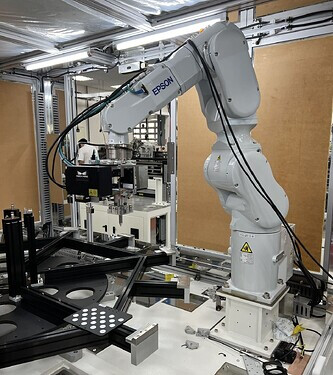
Remodeling refers to utilizing 3D design software, such as SolidWorks, to modify the joint orientations of the robot’s physical model. To use this method, please send three on-site photographs to the robot design engineering team or the Mech-Viz robot development supervisor.The three on-site photographs include screenshots of the current joint positions and TCP of the robot (on the teach pendant), and a photograph providing a complete view of the robot, as shown in the following figure.
The robot joint positions:

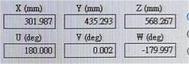
The robot TCP:
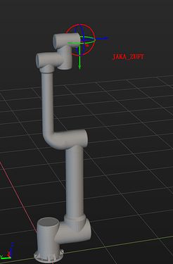
The complete robot view:
Case 1: JAKA_ZUFT
Issue
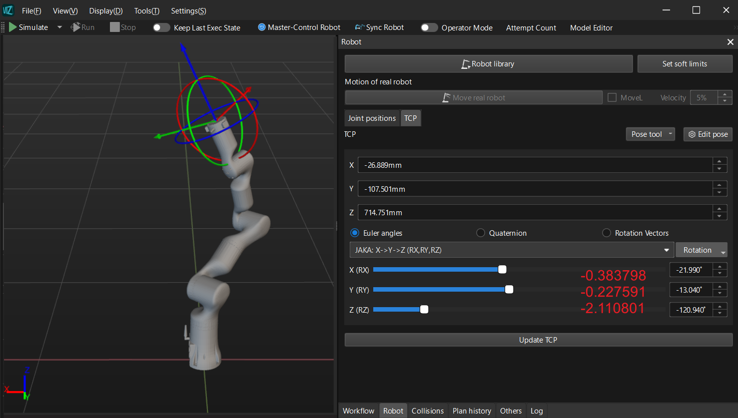
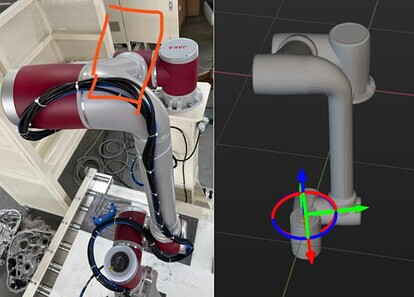
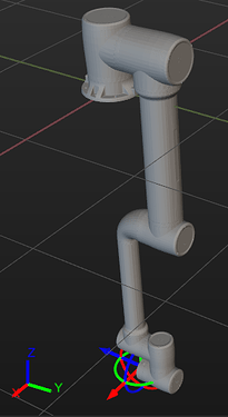
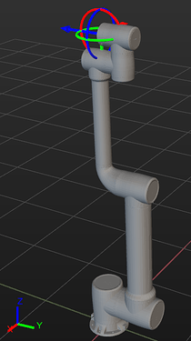
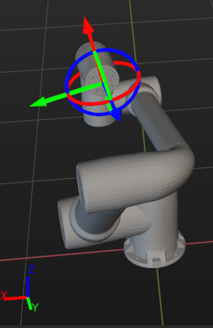
With the same joint position parameters (-80.076000, 148.791000, 117.936000, 3.272000, -90.000000, -80.076000), the J5 axis of the simulated robot in the software exhibits mirror symmetry to the actual robot’s J5 axis, as shown in the figure below.
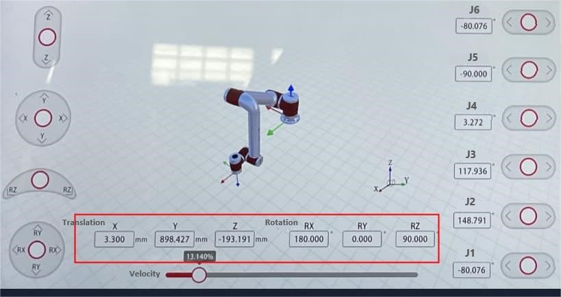
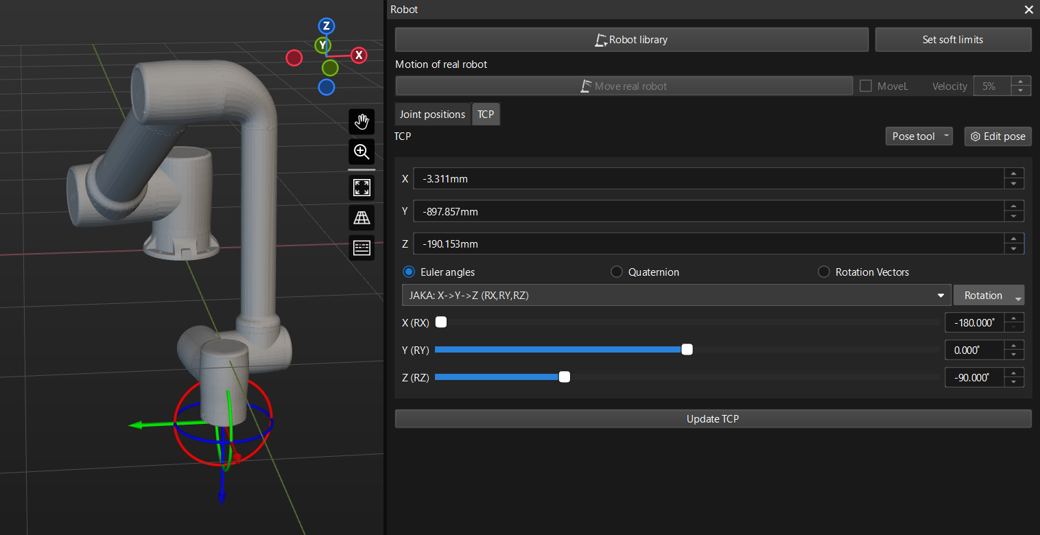
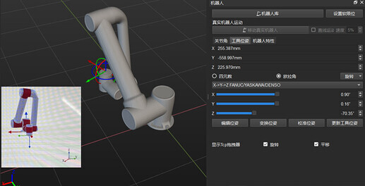
The simulated robot’s TCP values also show some symmetric deviations from the real robot, as illustrated in the figure below.

Troubleshooting
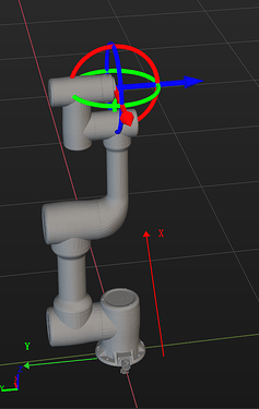
Based on the joint positions mentioned above, drag the slider of J5 in Mech-Viz to approximate the orientation of J5 axis to that of the real robot. The adjusted robot’s pose now aligns with the real robot, as shown in the figure below, but the TCP fails to correspond, with each value being mutually negative instead.
In Mech-Viz, choose another JAKA robot model as a reference. The selected model should match the configurations and pose of the actual robot. For this guide, we’ll use JAKA_ZU7 as the reference for comparison.
Note: It is advisable to confirm the initial pose of the selected robot through the teach pendant to avoid deviations arising from customer adjustments to the robot’s base frame direction.
In the robot HOME pose, compare the robot base frames with reference to the world reference frame, as well as the joint orientations between robot ZU7 and ZUFT.
JAKA_ZU7:
JAKA_ZUFT:
UR_UR5_Like:
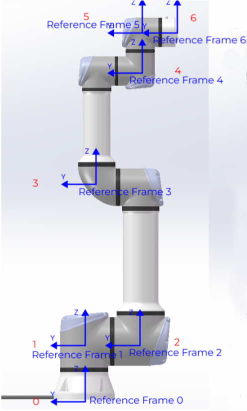
It is evident that JAKA_ZUFT is designed strictly according to the UR_UR5_Like robot configuration. Upon comparison with ZU7, we observed that in the ZUFT robot, the orientations of the X and Y axes for reference frames 0, 1, 2, 3, and 4 are incorrect.
Solution
Select at least one set of actual robot joint positions and TCP data from the teach pendant, as well as an image providing a complete view of the real robot.
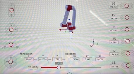
Information obtained from the teach pendant is as follows:
- Orientations of the XYZ axes of the robot base frame.
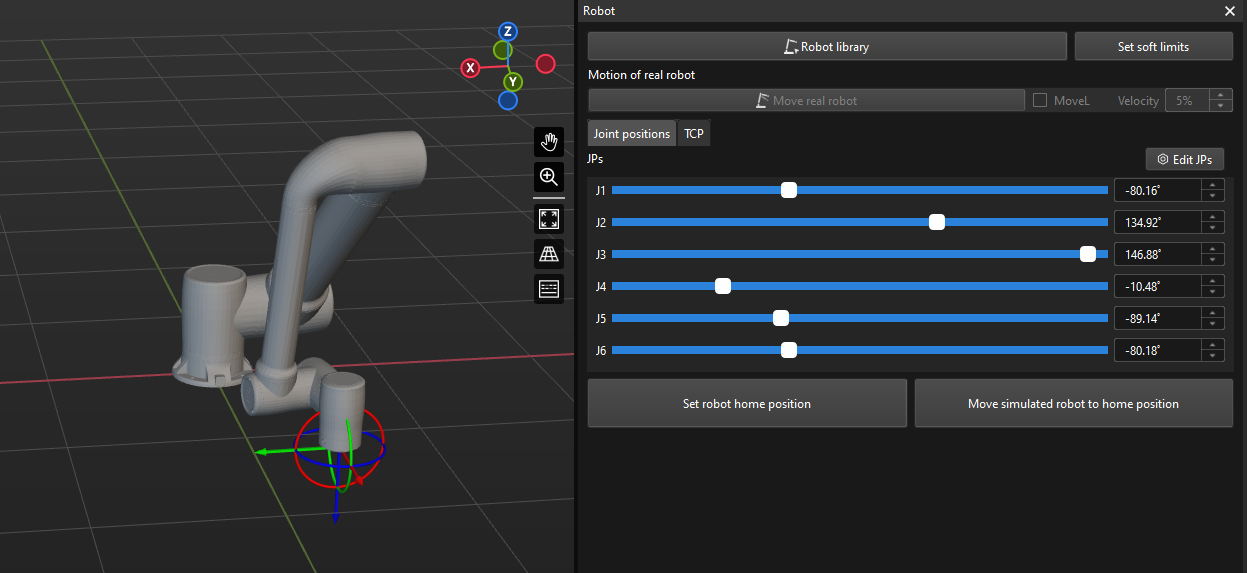
- Joint positions: -80.162, 134.916, 146.881, -10.481, -89.139, -80.182.
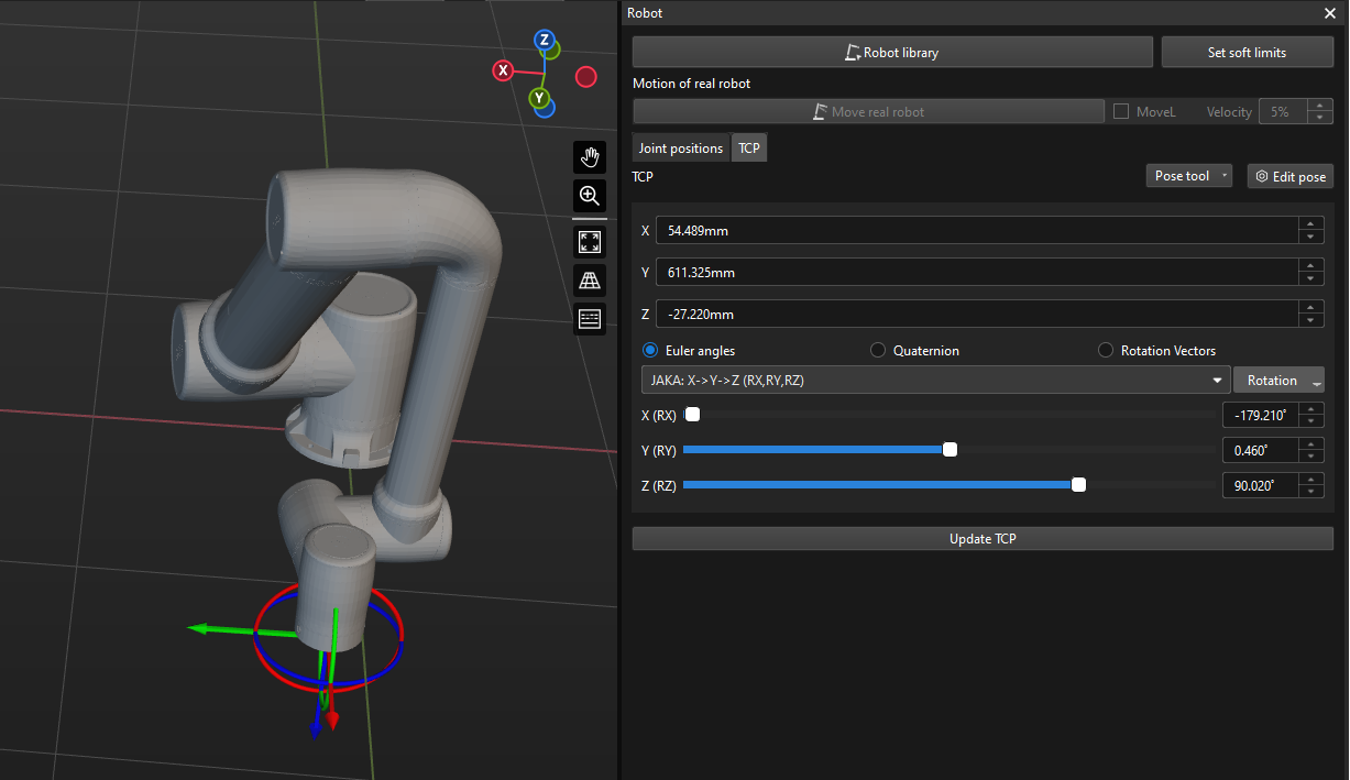
- TCP with these JPs: X=52.497mm, Y=613.324mm, Z=-27.221mm, RX=-179.206°, RY=0.458°, RZ=90.20°.
- Actual pose of the real robot at these JPs.
With this set of real robot data, we can use one of the following two methods to correct the ZUFT robot model in Mech-Viz.
Method A: Parameter adjusting
Parameter adjusting refers to the process of adjusting multiple sets of algorithm parameters based on the existing Mech-Viz robot model to match the real robot pose. The basic solution approach is outlined as follows:
Firstly, adjust the J1 axis pose at 0° by flipping it 180°, thereby mirroring the reference frame directions of axes J1, J2, J3, J4, J5, and J6. Then, adjust the J5 axis pose at 0° by flipping it 180° once again, further mirroring the reference frame directions of axes J5 and J6. J5 and J6 now return to their original poses, and the robot configuration aligns with the configuration of JAKA_ZU7. Finally, adjust the rotation direction of each axis (The real robot can be checked using the teach pendant).
Procedures:
-
Load the default JAKA_ZUFT model into Mech-Viz and input the joint positions (-80.162, 134.916, 146.881, -10.481, -89.139, -80.182). This case takes the UR_UR5_Like configuration and the algorithm parameter values of ZU7 as the initial pose for reference.
Note: It is recommended to adjust the Mech-Viz robot interface to align the robot base frame orientation of the robot model with that of the robot in the teach pendant for better comparison.
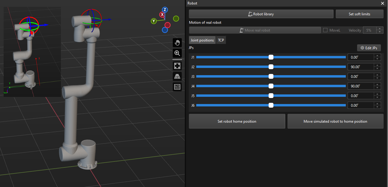
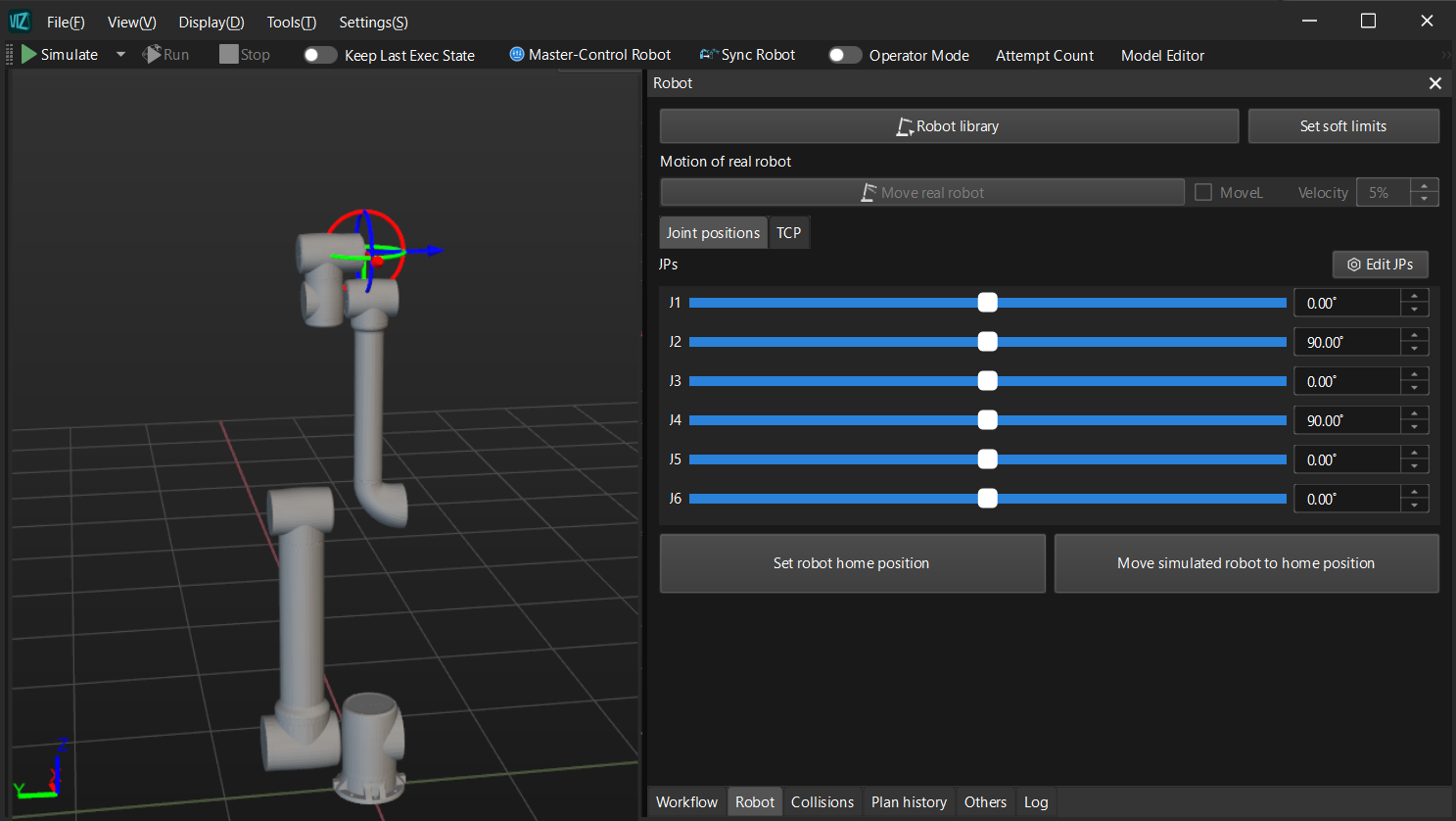
The default robot pose and algorithm parameter information for the added JAKA_ZUFT robot are as follows:
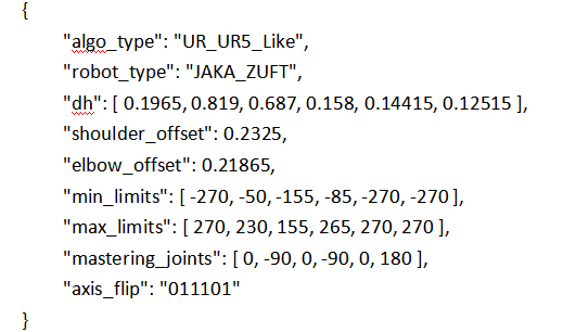
-
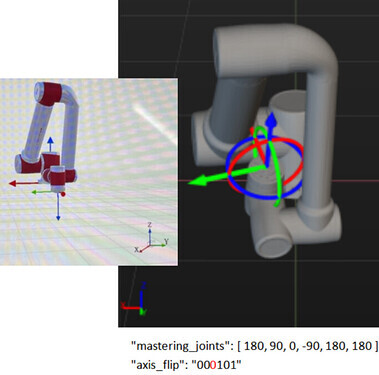
Adjust the poses of axes J1 and J5 at 0° by changing “mastering_joints”: [ 0, -90, 0, -90, 0, 180 ] to “mastering_joints”: [ 180, -90, 0, -90, 180, 180 ]. The Mech-Viz robot model configuration now aligns with the ZU7 configuration, as illustrated in the figure below (showing the modified initial configuration of JAKA_ZUFT).
Re-enter the joint positions, and the resulting robot pose is depicted in the figure below. Upon comparison with the actual robot pose, it becomes evident that the rotation direction of the J2 axis is reversed.
-
Adjust the rotation direction of the J2 axis by changing “axis_flip”: “011101” to “axis_flip”: “001101”. After reloading the robot model, a reversal of the J2 axis pose at 0° is observed, as depicted in the figure.
Therefore, it is necessary to adjust the J2 axis pose at 0° by changing “mastering_joints”: [ 180, -90, 0, -90, 180, 180 ] to “mastering_joints”: [ 180, 90, 0, -90, 180, 180 ]. This adjustment restores the initial robot configuration, as shown in the figure.
Re-enter the joint positions, and the resulting robot pose is depicted in the figure below.
-
It is observed that the rotation direction of the J3 axis is also reversed. Here, adjust the “axis_flip” parameter of the J3 axis according to the method outlined in step 3. The resulting robot pose and certain algorithm parameters are depicted in the figure below.
-
Next, it is found that the problem of the J4 axis is similar to the J2 axis. Likewise, adjust the parameters “axis_flip” and “mastering_joints” according to the method outlined in step 3, and the resulting robot pose is shown in the figure below. The Mech-Viz robot pose, including the TCP, now matches that of the robot in the teach pendant. The model correction is completed.
The complete algorithm parameter file at this point is as follows:
{
 "algo_type": "UR_UR5_Like",
 "robot_type": "JAKA_ZUFT",
 "dh": [ 0.19576, 0.81952, 0.6876, 0.15808, 0.14424, 0.12711 ],
 "shoulder_offset": 0.2365,
 "elbow_offset": 0.21865,
 "min_limits": [ -270, -50, -155, -85, -270, -270 ],
 "max_limits": [ 270, 230, 155, 265, 270, 270 ],
 "mastering_joints": [ 180, 90, 0, 90, 180, 180 ],
 "axis_flip": "000001"
}
As a precaution, it is recommended to compare TCPs with a few more sets of robot joint positions. The “dh” values of JAKA robots should be based on the teach pendant.


Method B: Remodeling
Remodeling refers to rebuilding the models of each joint of the robot and adjusting the reference frame directions. The basic solution is outlined as follows:
Utilize the robot numerical model and algorithm parameters to reassemble the robot model in SolidWorks, changing the orientation of the J5 axis. Then, establish the reference frames for each joint according to the JAKA_ZU7 configuration (keep the Z-axis orientation upward unchanged, only change the Y-axis orientation). Finally, reverse the values of DH parameters E, G, H in the algorithm and verify the rotation direction of each axis.
Procedures:
-
In SolidWorks, flip the orientation of the robot’s J5 axis to align the initial configuration with ZU7.
-
Create reference frames 0-6 of each axis for ZUFT based on the reference frame directions of ZU7 in Mech-Viz. After completing the creation, export the STL models of robot joints.
The initial pose and reference frame directions of ZU7:
The algorithm and configuration file of ZUFT created based on UR_UR5_Like robot configuration is as follows.
{ "algo_type": "UR_UR5_Like", "robot_type": "JAKA_ZUFT", "dh": [ 0.1965, 0.819, 0.687, 0.158, 0.14415, 0.12515 ], "shoulder_offset": 0.2325, "elbow_offset": 0.21865, "min_limits": [ -270, -50, -155, -85, -270, -270 ], "max_limits": [ 270, 230, 155, 265, 270, 270 ], "mastering_joints": [ 180, 90, 0, 90, 180, 180 ], "axis_flip": "000001" } -
Import the completed robot model into Mech-Viz. The imported robot model is as follows:
-
Adjust the robot algorithm parameters to restore the robot pose. From the above diagram, it is evident that the positions of the robot’s J2, J3, and J4 axes are misaligned. This discrepancy is due to the setting in the algorithm parameters that the adjustment is made for the positive direction of the Y-axis. To address this issue, make the values of J4 in “dh” ([J1, J2, J3, J4, J5, J6]), “shoulder_offset” value, and “elbow_offset” value negative.
-
Follow method A to adjust the “mastering_joints” and “axis_flip” parameter sets, and the final algorithm parameters for the robot are obtained as follows:
{
"algo_type": "UR_UR5_Like",
"robot_type": "JAKA_ZUFT",
"dh": [ 0.19576, 0.81952, 0.6876, -0.15808, 0.14424, 0.12711 ],
"shoulder_offset": -0.2365,
"elbow_offset": -0.21865,
"min_limits": [ -270, -50, -155, -85, -270, -270 ],
"max_limits": [ 270, 230, 155, 265, 270, 270 ],
"mastering_joints": [ 0, -90, 0, -90, 0, 180 ],
"axis_flip": "011101"
}
After the adjustments, re-enter the robot joint positions (-80.162, 134.916, 146.881, -10.481, -89.139, -80.182), and the TCP and robot pose at these joint positions are as shown in the figure below. The TCP now matches with that of the robot in the teach pendant.
Case 2: REALMAN_RM65_B
Issue
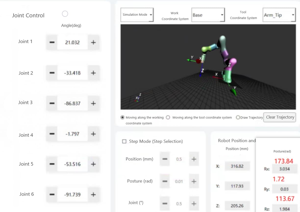
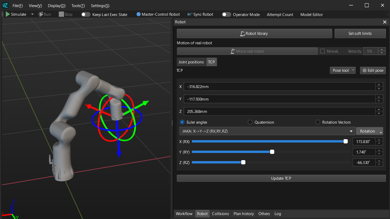
After inputting joint positions (21.032, -33.418, -86.837, -1.797, -53.516, -91.739) in Mech-Viz, it is observed that several joints of this robot exhibit a reversed pose in relation to the model, as shown in the following diagram.
Solution overview
To align the pose of the two robots at the same joint positions, first, align the initial robot pose between the simulated robot in Mech-Viz and the real robot. Then, collect multiple sets of joint positions from the teach pendant. Adjust the reference frame direction and rotation direction of the axes, and use the multiple sets of joint positions to verify the adjustment.
Procedures
Aligning the initial pose
The initial pose and robot reference frame of the real robot can be obtained through the teach pendant, as illustrated below.
As this brand of robot has not been previously adapted, the simulated robot can be loaded in Mech-Viz based on the SphericalWrist_SixAxis robot configuration.
In Mech-Viz, it is necessary to adjust the J3 axis pose at 0° in the initial configuration parameters to synchronize the initial pose of the robot. This adjustment ensures that the robot reference frames, the angles of each axis, and the flange reference frames match between the two robots. The modified robot model in Mech-Viz is illustrated in the following diagram.

Collecting the joint position data
Collect multiple sets of joint positions and TCPs for the Realman_RM65_B robot from the teach pendant, along with a complete view image of the robot. This guide collects the following two sets of data:
-
The first set of joint positions (50, 55, -75, 80, 20, -70) and TCP.
-
The second set of joint positions (22.346, -34.089, -87.427, -4.357, -59.03, -88.549) and TCP.

Adjusting the configuration parameters
-
Adjust the J6 axis pose at 0° by changing the “mastering_joints” parameter. The algorithm parameters are shown in the following figure.
-
Reduce the joint position values of each joint one by one on the teach pendant and observe the direction of joint rotation. At the same time, drag the sliders of each joint position to the left in Mech-Viz and compare whether the direction of rotation of each joint is consistent with the actual robot. If any joint is found to rotate in the opposite direction, interchange the “axis_flip” value of that joint between 0 and 1. The modified rotation direction parameters are: “axis_flip”: “011010”.
-
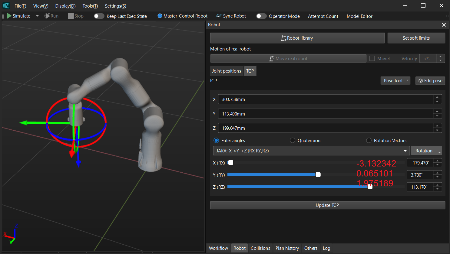
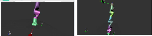
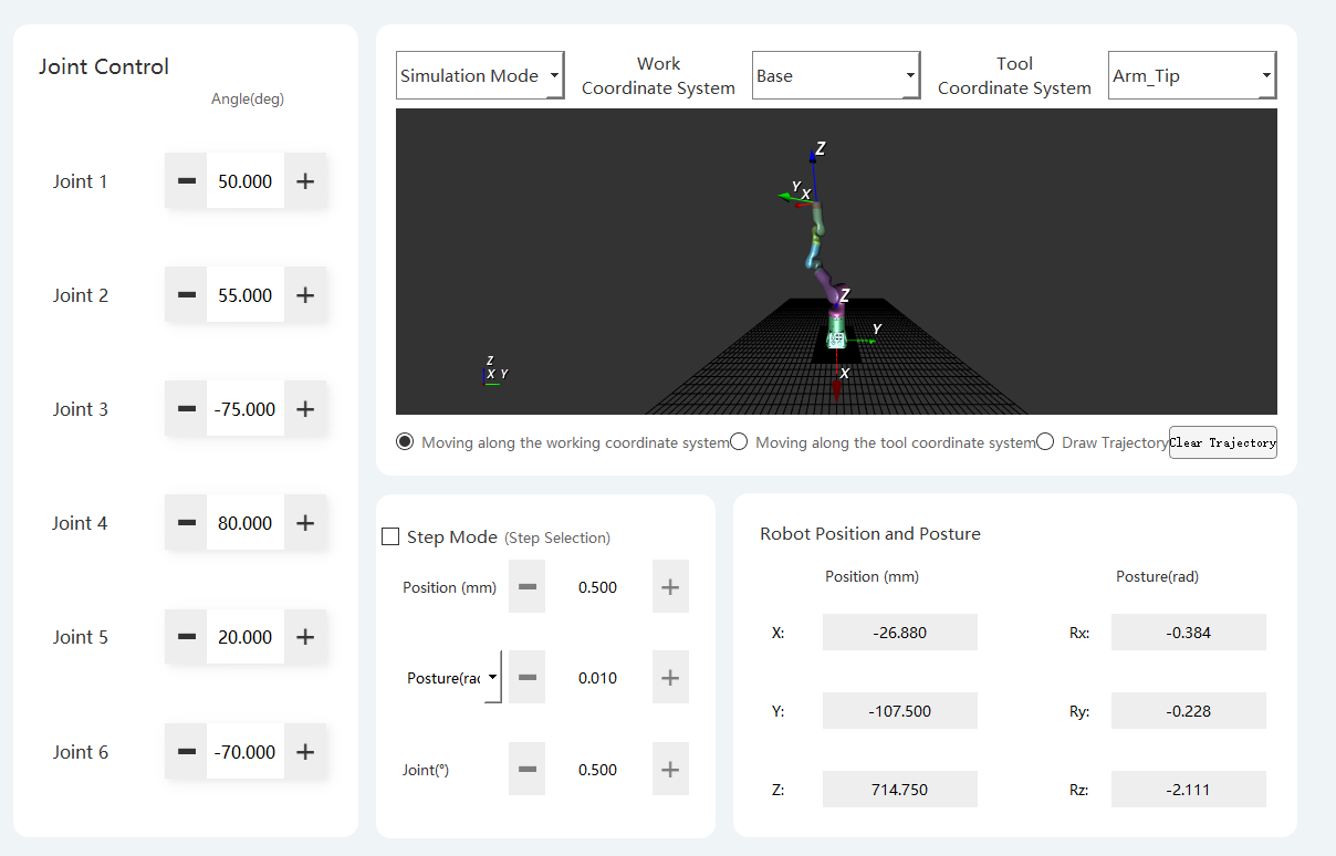
Re-enter the joint positions of the robot and verify if the poses and TCPs of the robot align. The comparison results shown in the following figures confirm that the robot’s poses and TCPs now match, indicating the completion of the model correction.
The pose and TCP of the Realman_RM65_B robot with the configuration adjusted (joint positions: 50, 55, -75, 80, 20, -70):
The pose and TCP of the Realman_RM65_B robot with the configuration adjusted (joint positions:
22.346, -34.089, -87.427, -4.357, -59.03, -88.549):
Note: The real robot’s RX value is 180.539°, while the RX value of the robot in Mech-Viz is -179.47°, indicating a small discrepancy. This is caused by the robot’s soft limits.