Introduction
Target Reader: Solution Engineers, Layout Planning Engineers, Mechanical Design Engineers, Mechanism Design Engineers, etc.
Post Overview: This post focuses on loading track links. It elaborates in detail on common challenges encountered in the industry, such as incoming materials for track links, picking, and corresponding solutions to address these challenges. This information provides significant guidance for the overall design of this solution, ensuring smooth progress through subsequent project phases.
Oil stains on object surface affecting picking
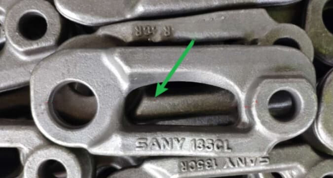
Issue: The incoming track links are coated with oil or release agent. After the gripper picks the object, it is easy to slip or even fall off, which seriously affects the picking stability and accuracy.
Solution: Manually clean the oil stains and release agent on the surface of the track link before loading to ensure a clean object surface for picking. Select the drive component with a high safety factor for the gripper fingers. Additionally, you can knurl the surfaces that the gripper fingers will pick to increase friction.
Burrs on object surface causing severe wear on gripper fingers
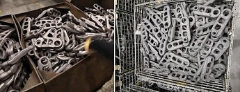
Issue: The incoming track links have a very rough surface, such as the burrs, concaves, and flashes on the surface, as shown in the figure below. This will lead to severe wear on gripper fingers.
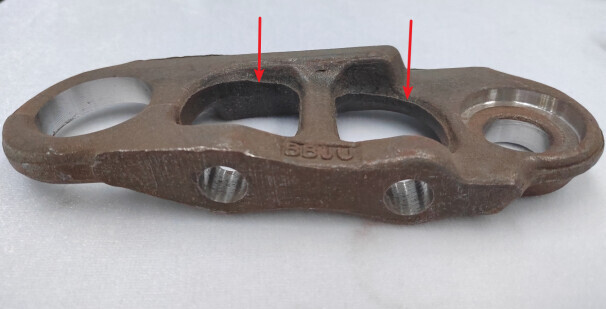
Solution: Find the right hardness for the gripper finger material to ensure both the picking stability and service life of gripper fingers. The part of the gripper fingers that comes into direct contact with the object should be detachable, which facilitates easy replacement and maintenance in the future.
Interlacing of track links affecting picking
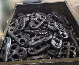
Issue: For track links with large hollow areas, if they are coming in a randomly stacked manner, they may interlace with each other. This will lead to collisions between the gripper and the track links on the next layer when picking from the current layer and even unintended picking of track links on the next layer.
Solution: Consider changing the pick points. Pick the outer surface or the circular hole. For scenarios where the track links have large hollow areas and they significantly interlace with each other, it is recommended to stack them in a relatively neat manner.
Poor strength of turnover box or bin
Issue: The side walls of the bin are welded from thin sheet metal or wire mesh. The following issues are encountered in actual use:
- The side walls of the bin become severely deformed after long-term use, such as protruding inwards or outwards. This will lead to interference when picking the track links.
- The point clouds on the upper edge of the bin’s side wall are sparse, making it difficult to accurately locate the bin when a dynamic bin is used.
Solution: The framework of the bin’s side walls should be welded from square bars or other high-strength materials. The skin should be welded from sheet metal or metal gratings. Ongoing inspection and maintenance are also needed during later use.
Inner walls of the bin interfering picking
Issue: The inner wall of the bin protrudes, as shown in the figure below. The robot interferes with the protruding parts after it picks the track link, leading to picking failure.
Solution: Adjust the bin to ensure that the inner walls of the bin are flat and without protruding parts. In this way, the above issue can be avoided.
Local accumulation of materials affecting recognition and picking
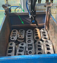
Issue: When other track links in the vicinity have been picked up, those accumulated in the corners of the bin still stand upright, leaning against the bin walls. Only point clouds of the object’s side can be recognized after the camera captures images and thus accurate picking poses cannot be obtained. The effects from the bin’s walls also prevent the gripper from successfully picking the track links.

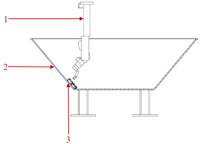
Solution: Adjust the bin’s structure to ensure successful image capturing and picking in the accumulated area. For details, refer to the figure below. 1. Gripper, 2. Bin, 3. Track link.