Introduction
Target Reader: Solution Engineers, Layout Planning Engineers, Mechanical Design Engineers, Mechanism Design Engineers, etc.
Post Overview: This post focuses on loading metal ingots. It elaborates in detail on common challenges encountered in the industry, such as incoming materials for metal ingots, picking, and corresponding solutions to address these challenges. This information provides significant guidance for the overall design of the solution, ensuring smooth progress through subsequent project phases.
Arrangement of metal ingots
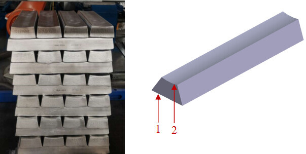
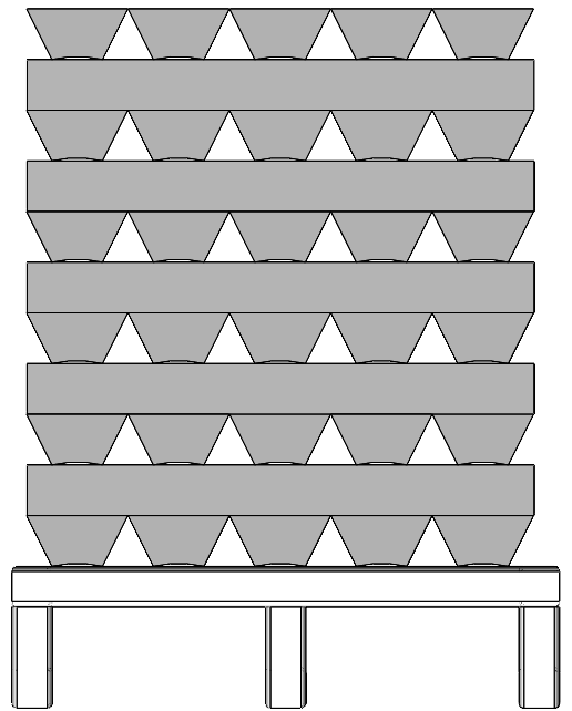
Issue: The common arrangement of metal ingots is shown in the following figure: The longer side of the metal ingot (see 1 in the figure) is at the bottom, and the shorter side (see 2 in the figure) is at the top. The gripper cannot effectively pick the metal ingots due to the large curvature of the surface corresponding to the short side, and the text and patterns on the surface.
Solution:
- When the space for picking and placing is large, you may use a clamp gripper.
- Adjust the arrangement of metal ingots. For example, place the longer side (see 1 in the figure) of the metal ingot at the top, and the shorter side (see 2 in the figure) at the bottom. Note: If the metal ingots are stacked compactly, the point cloud may not be segmented effectively.
Limited space in picking or placing position
Issue: The gripper picks the two end faces of the metal ingot, and then the robot moves the gripper to the position for loading. At this point, the gripper cannot open normally due to the interference with safety barriers on both sides of the conveyor line, and the metal ingots cannot be placed successfully, as shown in the figure below.
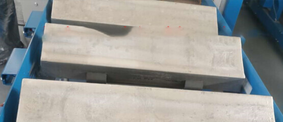
Solution: Appropriately increase the distance between the safety barriers to ensure that the gripper can open and close normally. In addition, if the space is limited, you may use a vacuum gripper.
Securing method with a stop block bracket
Issue: To ensure the overall strength and lifespan of the hardware at the loading position, the stop block bracket is fixedly connected with the camera bracket, secondary positioning platform bracket, etc. Due to frequent collisions between the incoming stacks and the stop block, the precision of the secondary positioning platform will decrease and the extrinsic parameters of the camera will drift after long-term use.
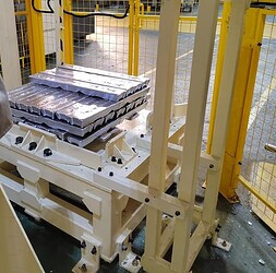
Solution: To ensure that the precision of the secondary positioning platform does not decrease and the camera parameters do not drift, the camera bracket, secondary positioning platform bracket, and stop block bracket should be independently positioned on the ground, ensuring they do not affect each other.