Mech-Vision 1.7.4
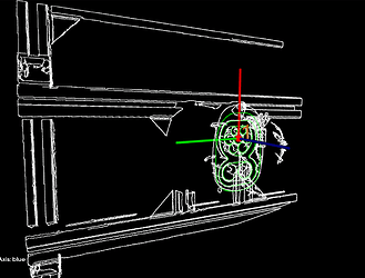
The setup is like this (with the correct matching result):
When “Filter Poses by Model Rotation Angle” is enabled, the poses are filtered incorrectly, which leads to matching the point cloud in the wrong, flipped orientation in “3D Workpiece Recognition” and an error in “3D Fine Matching Lite”.
When “Filter Poses by Model Rotation Angle” is not enabled the result is correct:
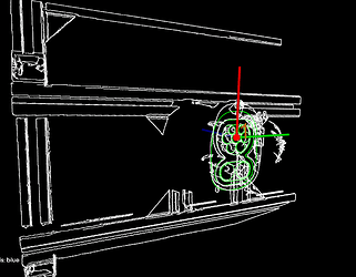
But once I enable it, then the result is incorrect because the pose is flipped 180°:

The angle used to calculate the rotation angle I would assume is the angle between the z-axis of the object and the negative z-axis of the camera, correct? I have the feeling that the angle between the camera and the object is used, which makes no sense as the objcet and the camera z-axis should point in opposite direction. Is this a bug?
It seems that there is no bug with the usage of “Filter Poses by Model Rotation Angle” after we checked. Your issue may be related to the matching model you were using. If possible, please upload your project file so that we can further help you to investigate.
Yes, sorry should have been attached:
Solution_Bug.7z (6.8 MB)
When you enable “Filter Poses by Model Rotation Angle” in 3d Workpiece Recognition you will see that the model is falsely flipped and if you enable it in 3d Fine Matching Lite there will be no output.
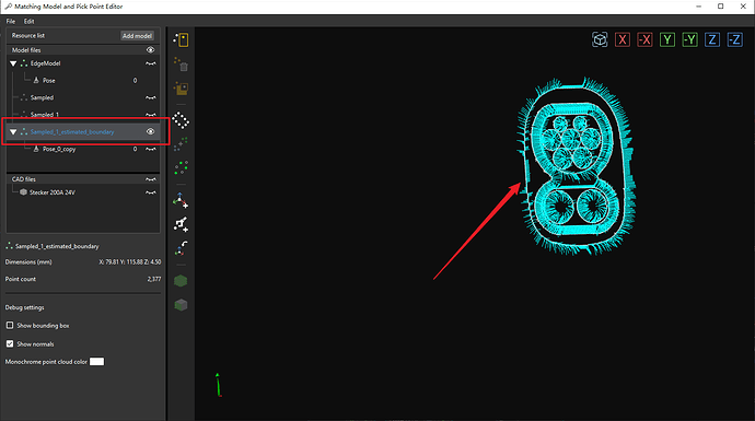
The normal vectors of your first matching model are incorrect, they are not perpendicular to the object’s surface.
But your second matching model is good, you can try using this model and enable “Filter Poses by Model Rotation Angle”, the poses will be filtered correctly.
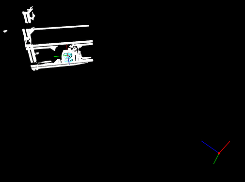
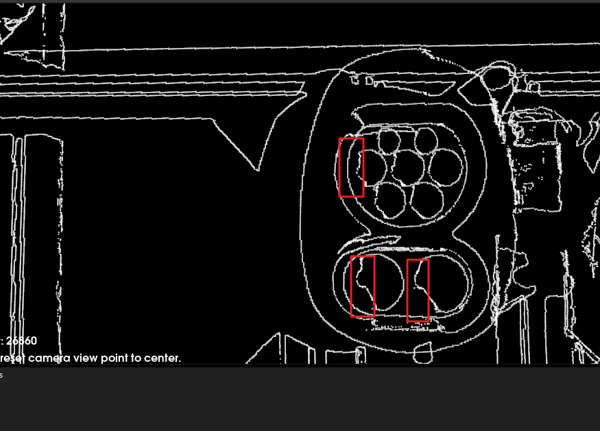
Besides, we found that the matching performance between the scene point cloud and the matching model you currently used was not satisfactory. You can see there was some point cloud loss for certain features of the workpiece, as shown in the figure below.
Maybe you can try using the surface matching mode, it seems we can have a better output by using the surface matching mode instead of the edge matching mode.
For instructions on how to generate a surface point cloud model, see Generate from Imported CAD Files.
Thanks for your insights.
“normal vectors of your first matching model are incorrect” - Yes, I agree but I find it unexpected behavior that when I create the point cloud via “Generate a Point Cloud of the outer surface” the normals are incorrect and if you use “Generate a Point Cloud from the current perspective” the normals are correct.
“But your second matching model is good, you can try using this model and enable “Filter Poses by Model Rotation Angle”, the poses will be filtered correctly” - I used this model already and the Poses are filtered incorrectly. I guess the algorithm uses the positive and not the camera’s negative z-axis as constraint axis and therefore the angle is wrong by 180°. The pose filter refers to the geo_center, no?
“Maybe you can try using the surface matching mode” - Good proposal. I will try a combination of edge and fine matching. If I use surface matching I am afraid that the model will be erroneously matched onto the car’s fender since this is also a flat area (if I cannot set a 3D ROI if the car has different position and I cannot localize the tank cap before)
For your first question regarding generating a point cloud, please allow us to have some further investigation, and we will reply to you as soon as we have the answer: )
For your second question, actually, “filter poses by model rotation angle” is based on the frame of the object used for generating the model, which is regarded as 0°. It filters poses by comparing the angle between the Z-axis of the workpiece model and the Z-axis of the real workpiece in the scene. For example, if the Z-axis of the workpiece used to generate the model is (0, 0, 1), and the rotation from the model to the scene results in a new Z-axis vector, let’s say (1, 0, 0). In this case, the angle between the new Z-axis and the old Z-axis is calculated to be 90°. Therefore, for your issue, the simplest solution is to rotate the frame of the grasping points in the model around the X-axis by 180°.
And we’ve updated your project using this method, please check it below:
Solution_Bug_updated.7z (6.8 MB)
Yes sure, take your time, no rush.
Ah okay, that is good to know and should be noted in the function blocks!
I would propose that using the “frame of the object used for generating the model” should be changed and be replaced by using the geo_center for two reasons:
- The reference frame cannot be changed easily. If you use a CAD Model you need to use a CAD program in order to change the reference frame of the model. If you only have a point cloud, you need to create a Vision project solely for the purpose of transforming the point cloud into another coordinate system. Both is Inconvenient for the user
- (Less imporant and my personal opinion) It is unintuitive to use the reference frame and not the geo_center as the poses from matching are always the geo_center. So one never has to deal with the reference frame.
By using the geo_center as pose to filter out the poses seems to me to be more intuitive and allows for more flexibility. What do you think?
Or alternatively in the Model Editor there is the possibilty to change the reference frame for each model.
Sure, we will add some descriptive information for this Step in Mech-Vision and our documentation, thanks for your feedback on this.
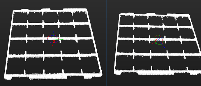
Actually, at the very first, we did use the geo_center of the model as a reference to calculate the rotation angle. However, later on, we found some cases where users were setting the geo_center somewhat arbitrarily, leading to incorrect pose filtering. The images below provide an example: the left image represents the expected direction of the geo_center, where the Z-axis is perpendicular to the upper surface of the workpiece, while the right image shows the geo_center set by the user, with a more arbitrary direction, which will ultimately affect the pose filtering results.
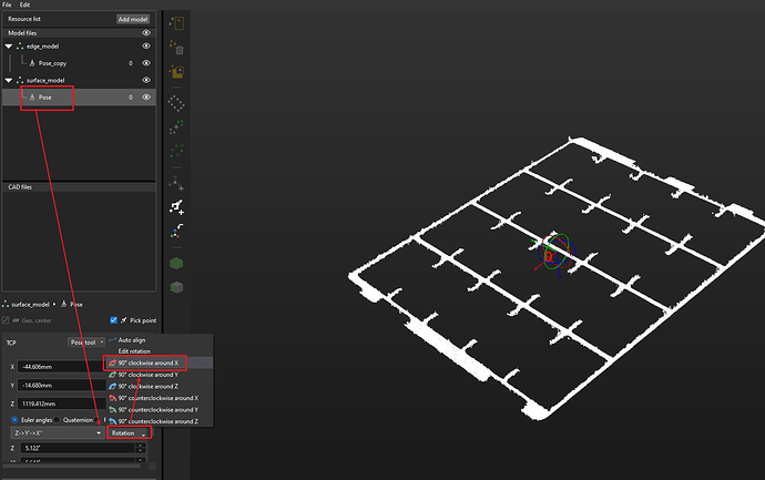
So now, instead of using geo_center, we have decided to use the reference frame of the workobject used to generate the model as the reference to calculate the rotation angle. However, to avoid cases like the one you encountered, we can flexibly adjust the frame direction of the geo_center of the model in the Matching Model and Pick Point Editor to the desired direction, as shown in the figure below, so that we can achieve satisfying pose filtering based on the model rotation angle.
Yes, but setting the geo_center as shown in the right image also makes no sense, since the pick pose (if pick pose = geo_center) cannot be reached since the gripper collides with the object.
But adjusting the frame direction of the geo_center has no effect on the reference frame of my model doesn’t it? The reference frame of the workobject (= frame of the object used for generating the model) != geo_center is it not?
In symmetry settings does the “Symmetry Axis” refer to the geo_center or the object’s reference frame?
I apologize for any confusion in my previous explanation. Let me clarify again. Your concerns can be divided into the following two points:
- The pose of your workpiece flipped 180° when using Filter Poses by Model Rotation Angle Step.
With this Step enabled, the Z-axis of your workpiece frame points downward to the upper surface of the workpiece. Therefore, we should rotate the pick point around the X-axis by 180° through the Matching Model and Pick Point Editor, so that the robot can match the pose and pick up the workpiece smoothly.
- The rotation angle calculation reference in the Filter Poses by Model Rotation Angle Step.
This step helps you avoid reverse matching in edge matching mode and is running normally. It compares the rotation angle between the reference frame of the workpiece used to create the matching model and the actual workpiece frame in the scene, and it has nothing to do with the pick point or the geo_center.
1 Like

