Camera bracket forms
| Fixed brackets | Aluminum profile brackets Square tube brackets Sliding camera bracket (horizontal) Vertical moving camera bracket |
| Arm-mounted brackets | Camera above robot’s J6 axis flange Camera below robot’s J6 axis flange |
Camera bracket design
Design of fixed brackets
Note: When designing fixed brackets, it is necessary to consider arranging grooves on the surface of the column to facilitate the routing of camera cables.
-
Aluminum profile bracket design
Construct the aluminum profile bracket using double-column aluminum profiles, and selected Euro standard 8080 aluminum profiles. The specific design is illustrated in the following diagram.
-
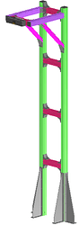
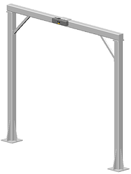
Square tube bracket design (recommended)
When using square tube brackets, it is necessary to weld them using hollow square tubes. Hollow square tubes have high strength and stability, providing a sturdy support frame. The design of the bracket can be a single-column or gantry structure (recommended) depending on the actual situation.- Single-column bracket design
Suitable for environments without significant vibrations. It features a simple structure and easy installation.
- Gantry bracket design
Suitable for environments with noticeable vibrations. The gantry structure provides a more stable support, better resisting external vibrations and impacts, ensuring the camera’s stability.
- Single-column bracket design
-
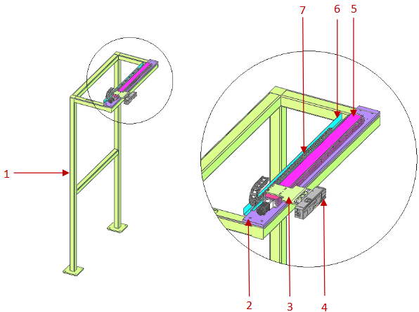
Sliding camera bracket design
Applicable scope: Adjacent stacks sharing the same camera.
Based on different power components, sliding camera brackets can be categorized into: servo module-type brackets and pneumatic cylinder-type brackets.-
Servo module-type bracket
Servo module-type brackets require smooth operation with no impact during stops and starts. The recommended normal operating speed is ≤250 mm/s. The composition of the servo module-type structure is as shown in the diagram below:
(1. Bracket body | 2. Module mounting plate | 3. Camera mounting plate | 4. Camera | 5. Servo module | 6. Cable chain mounting plate | 7. Cable chain)
Bracket body: Constructed by welding 100*100 square steel. Braces or other fixing methods can be added to increase the overall height of the bracket.
Module mounting plate and camera mounting plate: Designed with sufficient strength and rigidity to ensure the stability of the camera when the servo module is in operation.
Servo module: The repeat positioning accuracy of the servo module is generally categorized as ±0.01 mm, ±0.02 mm, ±0.05 mm, ±0.1 mm, ±0.2 mm, etc. Depending on the accuracy requirements of the actual project, an appropriate linear servo module with the required accuracy should be selected. It is recommended to use a servo motor for the drive part.
Cable chain: Choose standard off-the-shelf cable chains based on the total cable diameter. Typically, the cross-sectional area occupied by the total cables should be between 60% to 80% of the internal volume of the cable chain.
Cable chain mounting plate: Use bent sheet metal when necessary. -
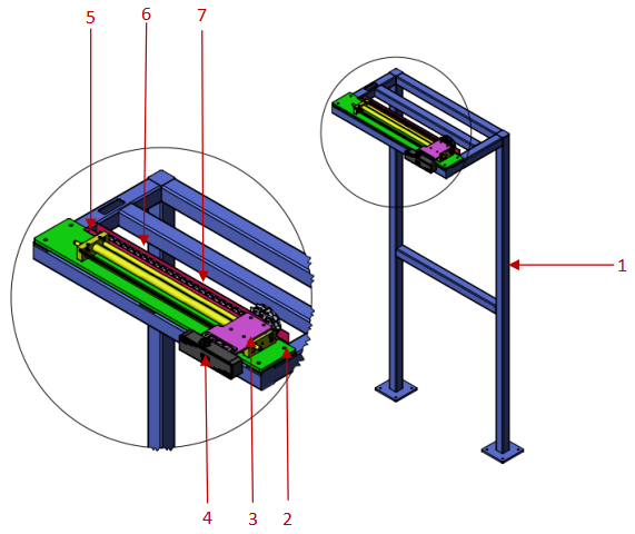
Pneumatic cylinder-type bracket (not recommended)
The positioning accuracy of the cylinder is slightly lower than that of the servo module, generally with an accuracy of ±0.1 mm. The bracket requires smooth operation with no impact during stops and starts. The recommended normal operating speed is ≤200 mm/s. The structure of the pneumatic cylinder-type bracket is as shown in the diagram below:
(1. Bracket body | 2. Cylinder mounting plate | 3. Camera mounting plate | 4. Camera | 5. Pneumatic cylinder | 6. Cable chain mounting plate | 7. Cable chain)
Pneumatic cylinder: The cylinder stroke should be selected based on the actual distance between stack positions on-site. It is recommended to choose a guided rod cylinder. Otherwise, it must be used in conjunction with a linear guide rail. Additionally, please note that the cylinder must be equipped with hydraulic cushioning, limit blocks, and exhaust throttle valves.
For the design and selection of the bracket body, cylinder mounting plate, camera mounting plate, cable chain mounting plate, and cable chain, refer to Servo Module-Type Bracket above.
Considering the impact of the cylinder, overall operational precision, vibration of the camera at docking positions, and long-term stability, this method is not recommended.
-
-
Vertical moving camera bracket design
Applicable scope: High stacking or excessively large length and width dimensions of the stacking structure, and poor point cloud quality for the bottom layer of stacked sacks.
Based on the driving force, vertical moving camera brackets can be categorized into: pneumatic vertical movement camera mounts and electric vertical movement camera mounts.-
Electric vertical movement camera mount
Design Requirements: The camera mount should operate smoothly without severe impacts during operation. The movement speed should be less than 250mm/s, and the motion mechanism should operate smoothly and seamlessly. Additionally, the camera mount should have sufficient rigidity to ensure no vibrations occur during operation. The composition of the electric vertical movement camera mount is as follows: 1. Mount body, 2. 3D camera, 3. Camera mounting plate, 4. Gear rack assembly, 5. Drag chain, and 6. Tank chain mounting plate.
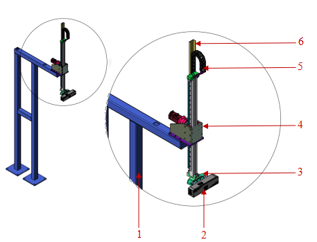
Gear Rack Assembly: It is recommended to choose a brake-equipped motor to prevent the camera from free-falling in the event of an unexpected power outage. -
Pneumatic vertical movement camera mount (not recommended)
Design Requirements: The camera mount should operate smoothly without severe impacts during operation. The movement speed should be less than 200mm/s, and the motion mechanism should operate smoothly and seamlessly. Additionally, the camera mount should have sufficient rigidity to ensure no vibrations occur during operation. The composition of the pneumatic vertical movement camera mount is as follows: 1. Mount body, 2. Camera mounting plate, 3. 3D camera, 4. Drag chain, 5. Rodless cylinder, and 6. Drag chain mounting plate.
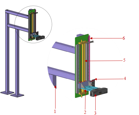
Cylinder: Select the cylinder stroke based on the actual distance between the stacks on-site. Additionally, please note: the cylinder must be equipped with an oil pressure cushion and limit block. Furthermore, the cylinder should be equipped with an exhaust throttle valve. Choose a closed-center control valve for the cylinder to ensure that the camera won’t experience free-fall movement due to gravity after air loss.Considering the impact of the cylinder, overall operational precision, vibrations at the camera’s docking position, and long-term stability, this approach is not recommended.
-
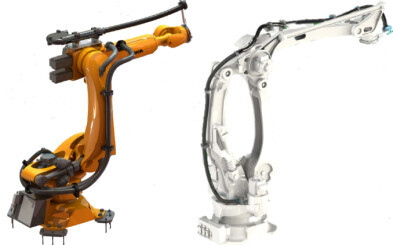
Design of arm-mounted brackets
Two common design forms
There are two common design forms for arm-mounted camera brackets: 1. Camera above the robot’s J6 axis flange 2. Camera below the robot’s J6 axis flange.
-
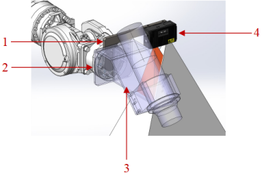
Camera above robot’s J6 axis flange
- Pros: When the robot arm’s reach is limited, raising the camera position can expand the field of view for image capturing.
- Cons: The rotation range of the robot’s J6 axis is restricted. During J6 axis rotation, interference may occur between the camera bracket or camera and the robot’s body.
In the diagram: 1. Camera | 2. Camera bracket | 3. Robot’s J6 axis flange
-
Camera below robot’s J6 axis flange
- Pros: The rotation of the robot’s J6 axis is not affected by the camera or camera bracket.
- Cons: Compared to the previous solution, when the robot is lifted to the same height, the camera’s image-capturing position’s is lower, resulting in a smaller field of view.
In the diagram: 1. Camera | 2. Camera bracket | 3. Robot’s J6 axis flange:
Notes for design
-
When designing an arm-mounted bracket, pay attention to the fixation and arrangement of camera cables. Refer to: Guidelines for mounting camera cables
-
Avoid obstructing the camera’s field of view by the held objects. Context: to optimize the overall cycle time, it is common to have the robot trigger the camera capture after picking up the target object (the goal is to integrate the visual computation time into the robot’s motion cycle).
-
Typically, the more components are joined, the lower the overall structure’s rigidity and stability. Therefore, when designing an arm-mounted camera bracket, avoid welding or hinging multiple structural components (as shown in the diagram).
-
Consider the overall strength of the bracket. Avoid situations where thin sheet metal (as in the bottom left image) or slender rods (as in the bottom right image) are directly used for construction.
-
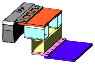
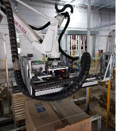
The camera and vibration device should be independently fixed on the robot flange. The camera and vibration device (grinding machine, screwdriver) are installed at the robot’s end simultaneously. During operation, vibrations are likely to cause drift in the internal and external parameters, and may even damage components inside the 3D camera. In the diagram below, where the camera and vibration device are installed separately at the robot’s end. In the image: 1. Camera mounting plate; 2. Robot flange; 3. Vibration device mounting plate; 4. Camera.
-
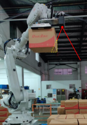
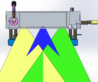
Avoid obstruction of the camera’s field of view by moving parts of the gripper: Install the 3D camera on the moving parts accessory to prevent the moving parts from obstructing the camera’s field of view under extreme conditions (as shown in the diagram below).

Installation requirements
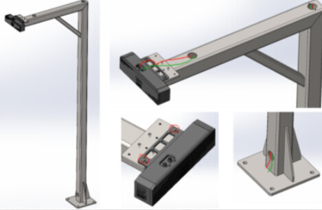
Installation requirements for fixed camera brackets
When installing a fixed camera bracket, pay attention to the following:
- Bracket fixation: You can use expansion bolts or chemical bolts to secure the camera bracket to the ground. These methods provide stable and reliable support, ensuring the camera remains stable.
- Number and type of anchor bolts: The number and type of anchor bolts depend on the height and structure of the bracket.
For installations not on the ground, the camera bracket may need reinforcement from the side walls or ceiling (as shown in the image below):
- Camera cable arrangement: Install the camera cables inside the cable slots arranged on the surface of the column for neat wiring. This ensures the safety, neatness, and ease of maintenance of the cables.
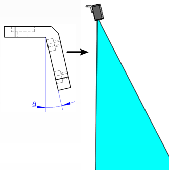
- Camera tilt: For project sites with restricted ceiling height, consider tilting the camera to improve the installation angle. However, during the initial project design phase, it is advisable to conduct simulations to ensure that the tilted camera angle meets the actual requirements.

In summary, stability, reliability, and cable arrangements are important factors to consider when designing camera brackets. Proper selection of fixation methods and cable arrangement ensures the stable installation of the camera and high-quality image capture.
Installation requirements for arm-mounted camera brackets
When installing an arm-mounted camera bracket, pay attention to the following:
-
Camera bracket installation
The camera bracket should be securely fastened, for example, by applying thread adhesive to the installation bolts or using anti-loosening washers. -
Cable fixing method
Cables near the connectors must be secured to prevent stress on the camera connectors.
When bundling cables, consider the rotational allowance of the robot’s end flange to avoid insufficient slack, which could lead to pulling on the camera cables and even cause irreversible damage to the camera cable connectors.
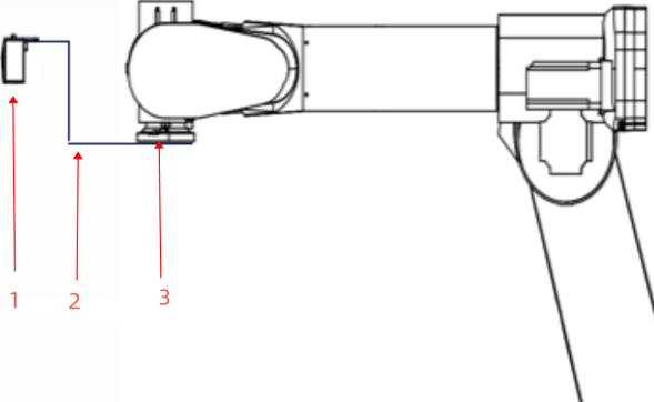
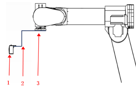
As shown (1. Camera cable | 2. Mounting base | 3. Cable connector | 4. L-shaped adapter | 5. Camera body):
-
Cable routing
The direction of cable routing should be arranged reasonably to avoid cables being excessively long or short within the cable sleeves.
-
Cable protection
It is necessary to use pipeline wrapping. Please note:- Do not use self-coiling cable conduits or cable cloth (self-coiling cable conduits or cable cloth cannot provide necessary torque protection and wear resistance, and have a short lifespan).
- Choose standard complete sets of corrugated pipe fittings for pipeline wrapping (including but not limited to: pipeline wrapping fixtures, clamps, friction balls, etc.).
- Securely fix and assemble the pipeline wrapping and cables separately to prevent additional torque on the cables during robot movement.