After selecting the robot you need in the Mech-Viz, it is recommended to first check the alignment of the robot TCPs and poses for the same joint position between the virtual robot in Mech-Viz and the real robot, to ensure that the robot parameters are valid.
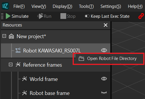
If there are discrepancies in the TCPs and poses between the two robots, it is necessary to modify the robot parameters. The robot parameters are saved in the robot configuration file [robot]_algo.json. Right-click on the robot name in the Resources to open the robot file directory and find the robot configuration file.
For detailed information on the robot configuration file, see Description of [robot]_algo.json file.
This tutorial uses a KAWASAKI_RS007L robot as an example:

Select the robot
Select the robot you need from the robot library in Mech-Viz.

View TCP and JPs
The Joint positions and TCP of the robot can be viewed on the Robot pane.

Jog the real robot
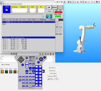
Jog each joint of the real robot to a random position (In this tutorial, we use a Kawasaki robot in robot simulation software as a substitute for a real robot).
Input JPs in Mech-Viz
Input the joint positions of the real robot into Mech-Viz and check if the virtual robot’s pose in Mech-Viz matches that of the real robot.

After the comparison, we found a relatively big difference between the two robots’ poses.
Troubleshooting
To make the robot parameters aligned, troubleshoot the issues in the following order:
- Orientation of the base frame
- Rotation of the axes
- Zero point of the axes
- Robot base frame
Orientation of the base frame
The real KAWASAKI_RS007L robot faces the positive Y-axis direction of its robot frame, while the virtual robot in Mech-Viz faces the positive X-axis direction of its robot frame.
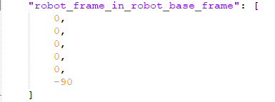
To make them aligned, we need to rotate the robot frame of the virtual robot in Mech-Viz around the Z-axis of its base frame by -90°. We can modify the Z-axis coordinate to -90 in the robot_frame_in_robot_base_frame attribute in the [robot]_algo.json file, as shown in the figure below.
For instructions on modifying the configuration file, see Write the [robot]_algo.json File.
Save the modification, then right-click on the robot name in the Resources in Mech-Viz to reload the robot.
After the modification, it can be observed in the figure below that the orientations of the two robot frames are now aligned. We can proceed to troubleshoot subsequent issues.

Rotation of the axes
Jog each joint of the robots separately and check if the real robot rotates in the same direction along each axis as in Mech-Viz.
If they are not in the same direction, switch the value of the upper and lower limits and reverse the positive and negative signs of the values at the same time in the axis_flip attribute in the robot configuration file.
Zero points of the axes
After adjusting the rotation of the axes, re-input the joint positions of the real robot into Mech-Viz and compare the difference between the two robots.

From the robot’s pose in the figure above, when the joint positions are the same, it is observed that J3 is off by 90°. So we need to change the J3 value in the mastering_joint attribute to 90, and reload the robot to check the difference.

As shown in the figure above, J6 also differs by 90°. So we also need to change the J6 value in the mastering_joint attribute to 90.

Now the robot poses are completely aligned for every joint position.
Robot base frame
Next, we need to align the TCPs of the two robots.
Note: Make sure that all the tool configurations have been removed on the teach pendant of the real robot.

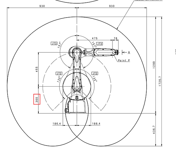
In the figure above, we found the coordinates of X and Y axes and Euler angle values match, but there is a 360 mm difference in Z-axis coordinates.
Upon checking the robot in the simulation software, we noted that the robot base frame is not located at the bottom of the robot but rather at the robot’s second-axis pivot.
Also, from the DH parameters in the specifications of the robot, we found that the DH1 value for the robot is 360, coinciding with the offset in Z-axis coordinates.
Therefore, we need to modify the Z-axis coordinate to 0.36 in the robot_frame_in_robot_base_frame attribute, as shown in the figure below, and reload the robot.
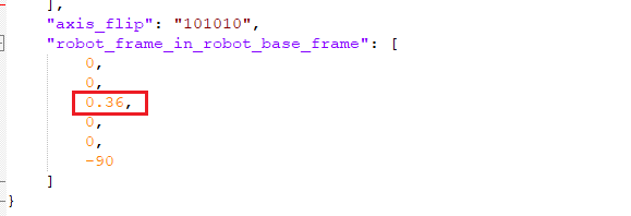
After the adjustment, we found that the TCPs of the two are now completely aligned.

Final check
Try entering another set of joint positions and, using the methods mentioned above, compare whether the TCPs and poses of the two robots are entirely consistent.

Through the comparison, it is confirmed that the two are entirely consistent, indicating the successful alignment of robot parameters.