Introduction
Target readers: solution engineers, layout planning engineers, mechanical design engineers, mechanism design engineers, commissioning engineers
Overview: This article works on the installation scenario of the sack depalletizing project. It provides detailed insights into specific requirements related to installation sites, lighting conditions, power supply, air supply, and camera dust prevention. This discussion guides the design of the entire depalletizing solution and the subsequent on-site installation.
1. Ground and Floor
When Mech-Mind’s vision system is applied in the logistics industry, it is often used in conjunction with robots, conveyor lines, and automated warehouses. Particularly, robots have specific requirements for the ground or floor. The detailed specifications are in the table below.
| Static load capacity | ≥3 T/㎡ |
| Material | Concrete |
| Concrete grade | Not lower than C30 |
| Pouring depth | Not less than 150 mm, recommended above 200 mm |
2. Installation Space
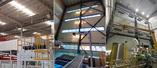
In practical sack depalletizing projects, we need to consider the requirements of the camera field of view, robot grabbing space, and other interference factors:
-
The clear height of the depalletizing station’s installation position should be no less than 4 meters. This is primarily to facilitate robot installation and construction, ensuring both camera visibility and robot maneuvering space.
-
Within the robot’s range of motion, columns or other obstructions should be avoided to ensure the robot’s freedom of movement and avoid limitations caused by obstacles.
-
When installing the camera, there should be no obstructions below the camera that interfere with its field of view. This ensures the camera can capture the target objects accurately and provide accurate vision information.
-
Mind the interference from main beams, secondary beams, firefighting water pipes, artificial light sources, or air ducts during camera installation. When planning the camera’s position, avoid these interferences to ensure the camera can be installed as required.
In summary, in sack depalletizing projects, when installing Mech-Mind’s 3D vision system, it’s essential to consider these factors thoroughly. Close collaboration with the design team, contractors, and relevant personnel is necessary to ensure the system’s proper placement.
3. Lighting
Lighting can significantly affect the image quality of a 3D camera. Here are some influencing factors:
Factor 1: Excessive Lighting
This factor can lead to overexposed images, making it difficult for the camera to capture clear 2D images and 3D point clouds.
Common sources of strong light in projects are illustrated in the image below:
Solution: Construct a shading canopy to control on-site lighting. Details: a comprehensive guide to shading solutions.
Factor 2: Uneven Lighting
This factor affects the effectiveness of deep learning.
In project scenarios, uneven lighting can appear as shown in the image below:

Solution: Generally, this issue can be improved by constructing a shading canopy or adding supplementary lights. Common supplementary lights include white ordinary LED strips or surface light sources with adjustable color temperature (6000k) and intensity.
Factor 3: Significant Difference in Illumination between Upper-Layer and Lower-Layer Sack Surfaces
When the stack height is ≥2m, the upper-layer sack surface is illuminated brightly while the lower-layer sack surface appears dark, as shown in the image below:
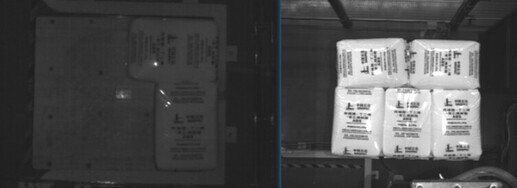
Solution: (1) Light from the side. (2) Add controllable light sources on the top.
4. Whole Station Power Supply (Reference)
| Power grid | TN-S system (Three-phase, five-wire system, 3-ph, N, PE) |
|---|---|
| Three-phase voltage | 380V AC, ± 10% |
| Frequency | 50Hz, ± 1Hz |
| Grounding | Use a common grounding method (resistance value not greater than 4Ω) |
| Power consumption | Not be less than 14kVA for each station |
5. Customer-Supplied Compressed Gas
- Dry, clean, and oil-free: To ensure the normal operation of the system and the lifespan of pneumatic components, compressed gas should be treated to be dry, clean, and free from oil contamination. This can be achieved by using suitable filters and dryers. Additionally, the compressed gas should not contain organic solvents, salts, or corrosive gases.
- Gas pressure: The operating pressure of compressed gas should be between 0.6 MPa and 0.8 MPa, and pressure fluctuations should be controlled within a range of less than 10%. This can be achieved by using appropriate pressure-regulating valves and stabilizing devices.
- Temperature and humidity: The temperature of compressed gas should be between -5°C and 70°C. When the temperature drops below 5°C, moisture removal is necessary to prevent freezing or other issues. Additionally, the relative humidity should be controlled below 80% to avoid excessive humidity affecting the system.
- Gas flow: Ensure an ample flow of compressed gas according to the selected pneumatic components and actual requirements. This can be achieved by designing the system rationally and selecting compressors of appropriate specifications.
In summary, for the use of compressed gas, dryness, cleanliness, and oil-free conditions are crucial requirements. Additionally, please ensure pressure stability, temperature control, and humidity control. Ensuring an adequate gas flow is essential to meet the system’s demands.
6. On-Site Dust
If the dust concentration on-site is too high (as shown in the image below), it can affect the operation of the entire station. Particularly, mind dust particles with a diameter below 2.5 mm, and implement effective dust prevention measures.
Since the equipment operates for an extended period, its surface temperature is higher than the ambient temperature. This can easily lead to dust particles adhering to the surface or exposed electrical interfaces (such as network ports and IO interfaces of industrial computers). This adhesion can cause poor contact in plugs or terminals, subsequently affecting signal quality. In severe cases, it can lead to short circuits in components inside the industrial computer.

Note:
Camera dust prevention measures: Depending on the specific on-site conditions, refer to Design of Camera Protective Devices in Extreme/Hostile Environments for designing protective devices for cameras.