In practical projects, it’s often necessary to obtain the STL model of a workpiece to generate point cloud models for matching, especially in disordered workpiece picking scenarios, where it’s even more widely used.
In the Mech-Vision software’s Matching Model and Pick Point Editor, you can directly import STL-formatted models.
As shown in the following diagram, click “Add model,” choose “Import CAD file,” and once the resource path interface pops up, find the desired STL file and double-click it. The diagram shows an imported STL file named “object_1”.

The usual approach is to select the STL model that needs to be operated on, and then click “Generate a point cloud of the CAD model’s outer surface” in the right-side function bar to produce the corresponding point cloud model.

The point cloud model generated after the operation is as follows.
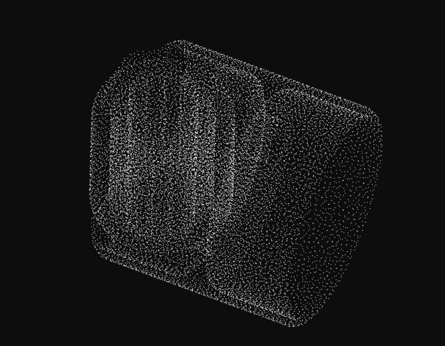
You can see that not only the external surface of the workpiece has a point cloud generated , but there are also corresponding points inside. This is because in the model structure, some internal parts also fall under the concept of “surface.”
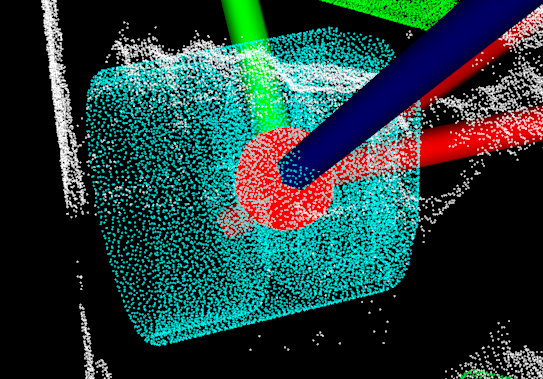
However, during the imaging process, the camera cannot capture certain “surfaces” inside, and the point cloud quantity inside occupies a relatively high proportion of the overall model. This can lead to matching errors, as shown in the diagram below, where the surface point cloud captured by the camera is misaligned with the model point cloud. This is because the model point cloud contains more points inside, and it results in a higher matching score when incorrectly aligned with the scene point cloud.
So, how can this issue be resolved? In reality, during camera’s image-capturing, no matter what pose the workpiece is in, only the external “surfaces” can be captured. In this scenario, the internal “surfaces” become interference in the model point cloud. To address this problem, we can use the “Generate Visible Point Cloud from Above” feature when generating the model point cloud instead of generating it directly. The specific steps are as follows:
- Click to select the model file you want to generate.
- Adjust the pose of the model.
- Click to generate the visible point cloud from above.
Repeat steps 2 and 3 for each orientation of the model’s faces. Finally, select all the generated point clouds and click “Merge point clouds.”


The merged point cloud obtained at the end is a point cloud model containing only the external “surfaces” of the workpiece.
This helps avoid matching discrepancies.
The actual result after the modification is as shown in the following diagram, where both vertical and horizontal poses can be accurately matched.
