For latest contents, refer to docs: Topic: Improving Application Cycle Time
Preface
Optimizing the cycle time is crucial for any project, as achieving the best solution at every step is the only way to attain the most efficient cycle time.
This post will explore methods for reducing the overall cycle time from the following four perspectives:
- Mech-Eye Viewer
- Mech-Vision
- Mech-Viz
- Other aspects
Mech-Eye Viewer
1. While ensuring stable capturing conditions, aim to minimize both the “Exposure Multiplier” and “Exposure Time”.
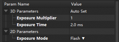
In 3D Parameters, reducing the values of “Exposure Multiplier” and “Exposure Time” will lead to shorter cycle times.
In 2D Parameters, the cycle time follows this order: “Flash” Exposure Mode < “Timed” Exposure Mode < “Auto” Exposure Mode.
When 2D images are unnecessary or acceptable, you can configure the “Exposure Mode” to Flash.
2. Upgrade Mech-Eye Viewer to the latest version and update the camera firmware to the most recent version.
Upgrading the firmware to the latest version significantly reduces the time required for capturing images.
For more information about the latest version software, see:
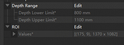
3. Adjust ROI and Depth Range
Define the necessary field of view for the project and exclude unnecessary regions and heights. This will reduce capture time.
4. Monitor camera network speed
During camera operation, monitor the transmission speed, which should ideally fall within the 700–800 Mbps range. If the speed is insufficient, please inspect the network of switches and IPCs to ensure they meet the standards for gigabit industrial networks.

Mech-Vision
1. “Capture Images from Camera”
-
Projects not requiring 2D processing need not be connected to the “Camera Color Image”.
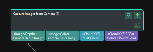
Removing the connection to the “Camera Color Image” can shorten the processing time for colored images. -
When Mech-Viz is not in use, a completion notification will be sent after image capturing.

Once capturing is complete, the robot can move to a designated point. Notifying the robot beforehand about the completion of capturing avoids waiting for the program to finish, thus reducing the overall cycle time.
2. Point cloud processing
-
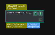
Remove excess point cloud
Utilizing the Step “Extract 3D Points in 3D ROI” to adjust 3D ROI Settings, along with Background Removal Settings in the Step “Capture Images from Camera” (right-click to Show all attributes), unnecessary background and point cloud data are eliminated. This process reduces the required time for subsequent point cloud processing, coarse matching, and fine matching.


-
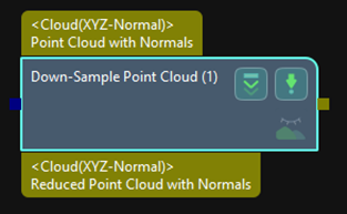
“Down-Sample Point Cloud”
While ensuring that recognition remains unaffected, employ the Step “Down-Sample Point Cloud” to appropriately reduce the quantity of point clouds. This action reduces the cycle time for subsequent Steps in the workflow.
3. Matching
-
Model selection

When feasible within the allowed features, “Edge matching” can be employed as a substitute for “Surface matching.” -
Coarse matching
Appropriately reducing the “Expected Point Count of Sampled Model” can lead to a decrease in processing time.
Mech-Viz
Note: Mech-Viz can lead to collision incidents when parameters are inadequate. Make adjustments only after conducting thorough testing to prevent collisions.
In this section, items marked with ※ are particularly important.
1.Time planning
-
Capture images in advance
Trigger the image capturing as early as possible after the mechanical arm moves away from the bin. -
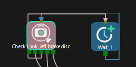
Reduce Wait Time
The detection signal does not require waiting. Check Wait Time for vision result self-loop, which typically falls below 50 ms.

2. Gripper and signal planning
-
Reduce Wait Time after using the gripper. (※)
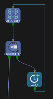

If the Wait Time is too short, it might lead to situations where picking and placing workpieces is unstable. Please ensure stability before making changes to this aspect. -
Preemptively activate suction cup airflow
When using a suction cup, its airflow requires time to activate. Preemptive activation not only accelerates the process but also avoids interference from touching other workpieces. -
Adjust gripper switch signals during movement
Modifying signals during movement enables smoother robot motion, preventing jerky behavior and reducing the overall project cycle time. -
Simplify the gripper model
A complex gripper model increases the time for collision calculations in Mech-Viz.
Consider using OBJ models instead of STL models and optimizing where parts are not involved in collisions. This optimization will speed up calculations in Mech-Viz.
3. Scene planning
-
Simplify scene model
Simplify intricate models to reduce calculation time when collisions will not be affected. -
Substitute fixed bin for dynamic ones (※)
By not requiring constant updates to the bin’s position, this approach can somewhat alleviate the time-consuming nature of Mech-Viz. However, it is crucial to ensure accurate loading positions before employing this technique.
4. Path planning
-
Reduce the rotation of the 6 axes of the robot
Some robotic arms exhibit slow rotation in their six axes, significantly affecting speed. By minimizing these actions, overall efficiency can be improved. -
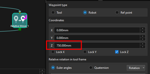
Lower the lift height of the Z-axis
While ensuring the viability of planning, efforts can be made to minimize relative movement distance, thus reducing time spent on movement.
-
Increase the Blend radius of transitional points
By enlarging the Blend radius, the path curvature becomes smoother, subsequently enhancing the robot’s movement speed.

-
Arrange intermediary waypoints appropriately
The positioning of intermediary waypoints should be reasonably close to both the picking and the placing waypoints. Path planning should ideally involve arranging the sequence as follows: picking waypoint → intermediary waypoint → placing waypoint. Additionally, it is preferable to keep the robot’s movement along a single axis throughout the entire process.
5. Operator Mode
Selecting the “Operator Mode” in Mech-Viz can enhance the speed of project execution.
Principle:
-
In “Operator Mode”, certain functions disabling collision detection are activated, including “Stop computing the current solution when the collision contact exceeds the threshold (for continuous operations)” and “Do not save in plan history (for continuous operations)”.
-
Point cloud display density is reduced, resulting in improved software operational efficiency.
Other aspects
1. Add payload to the robot
When the robot operates without any payload, its running speed is restricted. Incorporating the appropriate payload allows the robot to operate at higher speeds while delivering the same torque output.
2. Reinforce the equipment
This prevents equipment shaking caused by excessive robot motion speed.
3. Utilize a higher-configuration IPC
Upgrading the IPC’s performance can enhance image capture and transmission rates, leading to an estimated time savings of 0.2 to 0.5 seconds.
4. Introduce additional lighting
In cases of long exposure time, consider integrating external lighting to reduce internal exposure time, thereby reducing capture time.
5. Establish optimal capturing positions
During Eye In Hand calibration, setting impractical capturing angles might result in unnecessary rotation. Based on the workpiece’s pose, select a suitable capturing position to decrease the robot’s cycle time in each loading.


