Background
In projects with high accuracy requirements, the accuracy of the TCP will directly affect the accuracy of the robot’s performance. Therefore, after completing vision calibration and tool mounting, TCP calibration is necessary for the tool of the robot.
There are various methods for TCP calibration, and this passage mainly introduces KUKA’s four-point calibration method, where the coordinate axis orientations of the tool remain consistent with the coordinate axis orientations of the robot flange.
Procedures
-
Log on as an administrator
The default password for Administrator is kuka.
-
Select the four-point method
Open the Main menu on the teach pendant, click Calibrate → Tool → XYZ 4-point.
-
Select the tool
KUKA can store 16 tools in total. You can change the tool number in the first box to change which tool you are calibrating. Save your tool with a descriptive name.
-
Teach four points
Place a spike on a stable surface or the floor, and the tip of the spike is the calibration point. Jog the robot to move the tool’s tip to approach the calibration point, and click Touch-up on the screen to record the point.
Four points (P1-P4) are needed for the measurement in total.
Make sure as wide a variety of angles for the robot’s axes as possible when the tool moves between each measurement, especially for the fourth, fifth, and sixth axes.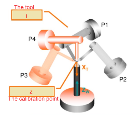
-
Save data
After teaching four points, click Save on the screen, and the robot will automatically calculate the TCP data. The error margin of the TCP calibration will be displayed on the screen in mm.An error margin below 0.3 mm is preferable. Follow the instructions below based on your calibration result:
- If the error margin is over 0.3 mm, perform the TCP calibration again.
- If the error margin is below 0.3 mm, click the Save button, then the TCP data will take effect. Meanwhile, remember to manually update the TCP data in Mech-Viz accordingly.
After obtaining a set of TCP data, you can manually change the Euler angles A, B, and C of the tool in the world frame to get multiple sets of TCP data, and check the discrepancy of the TCP errors. If there is a wide discrepancy, one possible reason could be that there is an offset in the zero points of the robot’s axes.


Screenshots in this passage are from the video below:
Tool Center Point Explained + Programming Tutorial | The Robotics Channel