1. Common Issues in Deep Bin Picking Scenarios
1.1 Unreasonable gripper designs
Unreasonable gripper designs will lead to interference with the scene or workpieces, failing to achieve the expected pick rate.
1.2 Excessive accuracy demands on grippers
Excessive accuracy demands on grippers require accurate poses of the workpieces or exact matching with a local feature of the workpieces. However, due to the randomness in incoming materials for deep bin picking scenarios, and the impact of workpiece characteristics (e.g., reflectivity) and overall accuracy of the production line, it is challenging to meet such accuracy requirements. This often results in issues such as picking failures, and workpieces dropping after being picked, and even affects the placements of workpieces.
1.3 Inappropriate accessory selection and layout
Inappropriate accessory selection and layout will lead to scratchings or even collisions during picking.
2. Solutions
2.1 Overall gripper design
The design of the gripper should consider the depth of the bin to ensure that workpieces can be picked under extreme conditions.
When picking workpieces at the bottom of a deep bin, ensure a safe distance (see h1 in the figure below) between the robot’s 6-axis end effector, camera, pipeline package, other gripper accessories, and the upper surface of the bin.
In the cases of tilted workpieces, mind the interference between the gripper and the bin, as well as other workpieces within the bin (see h2 and h3 in the figure below).
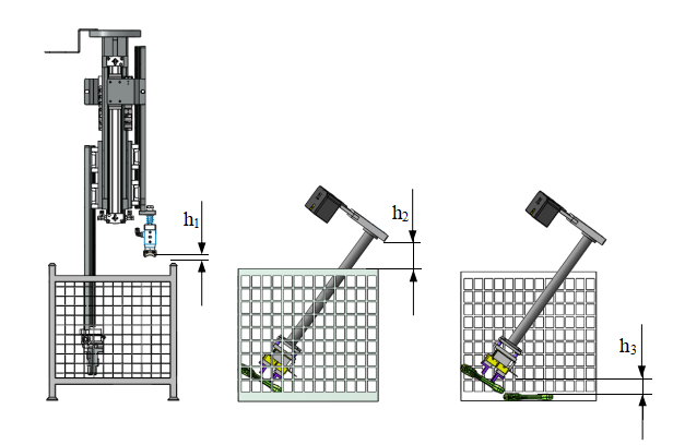
Generally, it is not recommended for the robot’s 5th and 6th axes to enter deep bins during picking, unless dealing with larger-sized workpieces in special bins (large dimensions in length and width, small dimensions in height).
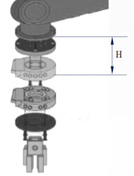
When a workstation needs to handle multiple models of workpieces, it is necessary to design multiple grippers. One common method of gripper switching is using quick-change plates.
Note:
- The quick-change plate accuracy may impact the picking accuracy of the gripper.
- The camera should not be involved in the gripper switching.
The installation area of the quick-change plate is the H as shown in the left picture below:
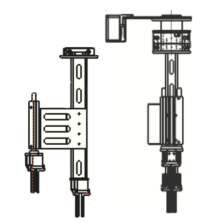
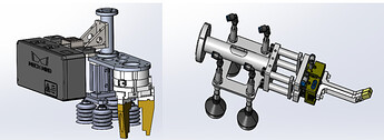
When multiple grippers and cameras are simultaneously installed at the gripper’s end effector, avoid the same directions for grippers and cameras, as shown in the diagram. For incoming tilted workpieces, an excessively long length in one direction of the gripper can lead to collisions between the gripper and the bin during picking.
Recommended installations for multiple grippers and cameras:
2.2 Floating mechanism
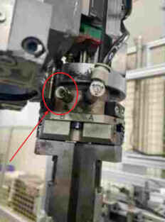
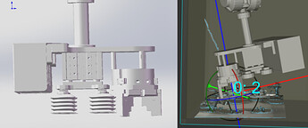
For grippers with excessively high accuracy requirements, consider using a floating mechanism as illustrated in the figure below.
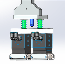
The design of the floating mechanism should ensure that it can freely switch between the “floating state” and the “non-floating state”. After picking a workpiece, the gripper should immediately return to where it was before picking. Additionally, when the gripper is in a “floating” state, it should remain fixed in directions where floating is not required, such as the Z-axis direction (see the example below).
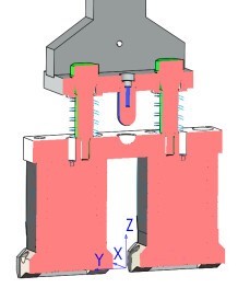
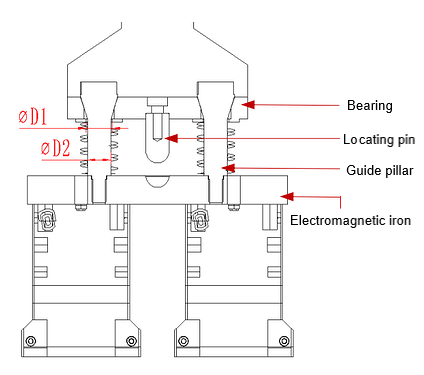
In the figure above is an electromagnetic gripper: the guide dimension D1 of the bearing is much larger than the dimension D2 of the guide pillar, and a spring is installed between the bearing and the electromagnetic iron.
During picking, the entire gripper presses down. Upon contact with the workpiece, the electromagnetic iron will lift the guide pillar, compressing the spring. At this point, the gripper is in the “floating state”, which involves several following aspects:
- The locating pin is inserted into the semicircular groove on the upper surface of the electromagnet to fix the gripper in the Z-axis direction, ensuring that the electromagnet gripper can successfully absorb the workpiece after being energized.
- Electromagnetic iron 4 is compliant around the X, Y, and Z axes.
- The gripper has a slight compliance around the X and Y axes.
When the electromagnetic iron is powered, the workpiece is picked, then the gripper moves upward. After the spring resets, the gripper returns to where it was before the picking.
2.3 Accessories
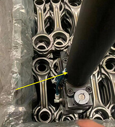
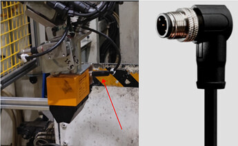
In the initial design phase of grippers, careful consideration should be given to the installation methods of gripper end components such as pneumatic connectors and electrical junctions, as well as the arrangement of cables and pneumatic tubes.
Whenever possible, employ top-exit methods for quick connectors, aviation plugs, etc. If cables or pneumatic tubes need to exit from the side of the gripper, preferentially choose “L”-shaped connectors.
Ensure a compact layout of cables and pneumatic lines. The space inside the gripper with the “hollow design” can be made use of.