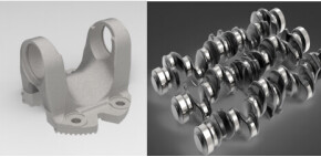
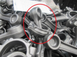
Specially shaped workpieces refer to workpieces with irregular shapes, including crankshafts, steering knuckles, and enclosure parts. Different from regular parts, the poses of specially shaped workpieces vary greatly in the infeed process, and they are likely to overlap and hook each other. As a result, picking such workpieces is difficult. The proper design of grippers, therefore, is crucial.
1. Confirmation checklist
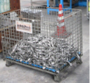
Carrying medium of incoming materials
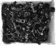
- Carrying medium of incoming materials: Pallets, trays, shallow and deep bins, and racks. The rough form and dimension of bins (such as mesh containers and plates) should also be considered as some will affect the workpiece-picking process (as shown below).
- Confirm whether there are partitions; if so, are partitions also the picking targets? With such information, you can determine whether the gripper should be designed to have multiple functions.
- Confirm whether manual intervention is involved in the picking process and whether there is any requirement on the bin clearance rate.
Requirements for material placement
- Case 1: After picking, the gripper can place the workpieces randomly, without any consideration of the workpiece orientation and pose. It is easy to design such grippers.
- Case 2: The gripper should be able to place the workpieces in specified orientations and poses. Thus, external devices, such as a flipping mechanism, might be added to satisfy such a requirement.
- Case 3: The gripper should place workpieces strictly following relevant requirements. It is a great challenge to design such a gripper. In most cases, workaround equipment such as the 2D camera and flipping devices should be added.
Requirement for picking cycle time
- The picking cycle time should meet the requirements of upstream and downstream processes and user demand.
- The cycle time can greatly influence the design of grippers. If the picking cycle time is short, you should ensure the picking process is stable at high acceleration and speed.
2. Gripper design
Key points for the design of the following common grippers:
Vacuum gripper
- Select vacuum equipment, especially the gripper and vacuum system, according to the weight of the workpiece and the pick points.
- For a higher picking success rate, it is recommended to design as many positions for picking as possible.
- Select a vacuum gripper according to the features of the picking surface (smoothness, the presence of leaking holes, etc.) for firm picking.
- The gripper should pick workpieces at a point as close to their center of gravity as possible to avoid the flipping of workpieces after picking and thus lower the possibility of dropping the workpieces.
- Generally, it is required to add the dropped-workpiece detection feature so that the problem can be dealt with in time without causing any other problems.
- There should be some safety margins (especially in the case where workpieces may flip after being picked). The gripping force should be appropriate so that workpieces remain intact.
- It is not recommended to use a vacuum gripper for cases requiring high picking accuracy.
Electromagnetic gripper
- Select an electromagnetic gripper according to the weight of the workpiece. The gripping force should remain moderate to avoid picking multiple workpieces at a time.
- For a higher picking success rate, it is recommended to design as many positions for picking as possible.
- The gripper should pick workpieces at a point as close to their center of gravity as possible to avoid the flipping of workpieces after picking and thus lower the possibility of dropping the workpieces.
- Generally, it is required to add the dropped-workpiece detection feature so that the problem can be dealt with in time without causing any other problems.
- Regular electromagnet: It is generally recommended that the rated gripping force should be more than ten times the weight of a workpiece. Electro-permanent magnet: The safety factor is usually within the range of 3–5 according to the surface conditions of workpieces.
Claw Gripper
- Select a claw gripper according to the weight of the workpiece. Note that there should be some safety margins.
- For a higher picking success rate, it is recommended to design as many positions for picking as possible, and the gripper is not limited to the expansion gripper and finger gripper.
- The gripper should pick workpieces at a point as close to their center of gravity as possible to avoid the flipping of workpieces after picking and thus lower the possibility of dropping the workpieces. Moreover, the gripper fingers can be knurled to increase the friction.
- Generally, it is recommended to add the dropped-workpiece detection feature so that the problem can be dealt with in time without causing any other problems.
- The fingers of a gripper should be compatible. The stroke per finger should be more than 2 mm to prevent variations caused by the tolerance of parts.
3. Application examples
- Workpiece: steering knuckle with a weight of 5.7 kg.
- Workpiece features: The steering knuckle is a specially shaped workpiece, a casting, which cannot be picked by means of magnetic force due to the restriction of subsequent processes.
- Carrying medium: deep bin
- Bin features: with a dimension of 1000 x 800 x 700 mm, a mesh container padded with a regular board.
- Poses of steering knuckles: random.
- Picking cycle time: around 30 s (including the image-capturing time).
Select a gripper
- If a workpiece has a complex shape and no appropriate picking surface, the vacuum gripper should not be selected.
- If the workpiece cannot be magnified, the electromagnetic gripper should not be selected.
Select the gripper cylinder
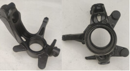
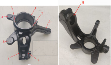
The selection of pick points: As the workpiece is specially shaped, the designed pick points for successful picking are shown below, where 1 and 9 can be used by an expansion gripper, and 2, 3, 4, 5, 6, 7, and 8 can be used by a finger gripper. Given the weight of the workpiece and the dimensions of positions for picking, a standard pneumatic gripper, with a stroke of 13 mm per finger and a gripping force of 1080 N, can be selected.
Design of non-standard gripper components
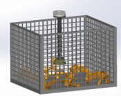
- Given the depth of the deep bin and the overall dimension of the workpiece, the rod connecting the gripper cylinder and the flange of the robot is extended to ensure that the fifth and sixth axes of the robot do not enter the bin.
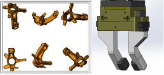
- If a steering knuckle is in the corner or the edge of the bin, the gripper fingers should be offset to pick it up. You can adjust the offset angle of gripper fingers and add replaceable blocks (the black blocks shown in the right figure below) to achieve picking in such cases.
Install accessories
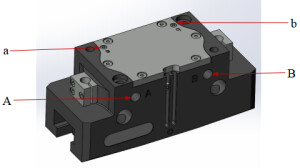
As collision with surroundings might occur when the gripper picks workpieces in a deep bin, the air inlets are designed on the top of the gripper, instead of the sides, to ensure that the gripper sides are flat without any fittings, thus avoiding possible collision and protecting fittings. In the figure below, a and b represent air inlets that control the gripper to open; A and B represent air inlets that control the gripper to close.
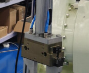
The connecting rod is designed to be hollow, within which the air pipes and cables are placed. Such a design can make sure the air pipes and cables are firm and stable and reduce the possible collision points on the surface of the gripper.
- This is helpful.
- This does not solve my issue.