We recommend that you read this article first: Brief Introduction to the Concepts of 3D Vision System: Base Reference Frame (aka. Coordinate System)
Pose
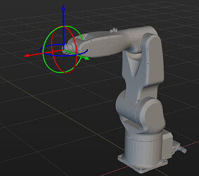
Pose refers to position + orientation. A rigid body in space has six degrees of freedom, divided into three translational and three rotational.
The end-effector position and orientation of a robot can be described using two methods: tool center point (TCP) and joint positions (JPs).
Tool Center Point (TCP)
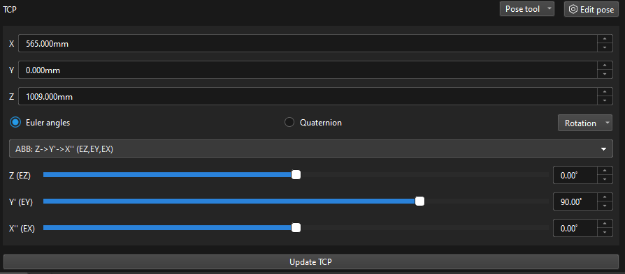
Tool pose represents the position and orientation of the tool reference frame in the robot’s reference frame. It consists of two components:
- Coordinates (XYZ) representing the position.
- Representation of rotation, which can be Euler angles, quaterniona, or rotation vector.
Flange Pose
The flange pose represents the position and orientation of the robot’s flange reference frame in the robot’s reference frame. Its representation method is the same as the TCP and can be considered a special tool pose where the tool’s center point is located at the flange center with no rotation.
Different manufacturers have different default orientations for the flange reference frame, leading to varying default angles for the flange pose. For example, ABB defaults the X-axis downwards, while FANUC defaults the X-axis upwards.
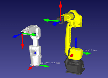
For most manufacturers, the flange pose has the Z-axis perpendicular to the flange surface pointing outward. However, Turing has the X-axis pointing outward.
Representations of Orientation in Space
There are various ways to describe an orientation in space, with Euler angles, quaternions, and rotation vectors being commonly used representations in industrial robots.
Euler Angles
Euler angles are a geometric concept that seems simple but is actually complex. We don’t need to delve too deeply into it; we just need to understand that:
- Euler angles are used to represent an orientation in space, but using only three angles is not sufficient. It’s also necessary to specify the rotation axis and rotation sequence. In other words, the same spatial orientation can be represented using multiple sets of Euler angles, making the representation non-unique.
- There are many different ways to define Euler angles. To avoid ambiguity, each robot brand typically selects a specific Euler angle definition.
For example:
-
ABB uses:

-
FANUC uses:

Mech-Viz software has compiled common Euler angle selections for different robot brands and automatically switches to the corresponding Euler angles when users switch between robots.
Quaternions
To avoid the problem of multiple solutions associated with using Euler angles to represent spatial orientations, some robot manufacturers opt for quaternions to describe orientations in space. Quaternions are roughly defined as using three numbers to define a spatial rotation axis and one remaining number to define an angle. Rotating the robot’s base reference frame from its default orientation around this rotation axis by this angle will reach the desired orientation.
Although quaternions do not suffer from the issue of multiple solutions of Euler angles and are convenient for communication due to their four numerical values, they are not widely adopted because they are less intuitive and harder to understand compared to Euler angles.
Rotation Vectors
Rotation vectors, also known as axis-angle representation, are the third form of representing orientations in space. This representation is relatively abstract. Currently, only Universal Robots (UR) uses this method.
Summary
Euler angles, quaternions, and rotation vectors are different methods for describing spatial orientations, and they can be converted into each other.
Joint Positions (JPs)
Using the angles of each axis of the robot to represent the robot’s orientation can uniquely determine the robot’s TCP.
