Robot Base Reference Frame
The robot base reference frame, as defined by the robot manufacturer, is rigidly attached to the robot body and can be used to describe the reference frame of the robot flange position.
This reference frame is the default reference frame inside the robot teach pendant. When receiving a robot provided by the customer, it is recommended to confirm whether the robot uses the base reference frame or other user-defined reference frames. If it is using a different reference frame, switch it back to the base reference frame before deploying the vision system. Within the Mech-Viz software, this reference frame is also used as the origin for the robot, indicating the position of the tool center point of the robot, that is, the tool pose.
Where Is Robot Reference Frame
The definition of the robot reference frame is determined by the manufacturer and may not necessarily be located beneath the robot base. Taking the five major families as examples:
- ABB: Located beneath the base.
- FANUC: Not beneath the base; positioned in a second-axis rotational plane.
- KAWASAKI: R-series in a one-axis rotational plane; others beneath the base.
- KUKA: Beneath the base.
- YASKAWA: Not beneath the base; positioned in a second-axis rotational plane.

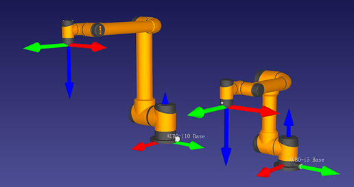
The robot’s base reference frame position is not limited to being just beneath the base or in the second axis rotational plane. For instance, in AUBO i5 and in some models from other major families, the robot reference frame is located approximately 2mm to 1cm above the base.
Robot Base Reference Frame Orientation
In addition to the position, the orientation of the robot’s base reference frame’s axes varies among different manufacturers. Using the five major families as examples:
- ABB, FANUC, KUKA, YASKAWA: X-axis points towards the front of the robot.
- KAWASAKI: Y-axis points towards the front of the robot.
Summary
Due to the randomness and uncertainty in how different manufacturers define the robot reference frame, we cannot currently guarantee that the base reference frame definitions for all robots in the Mech-Viz software are correct. This disparity is reflected in differences between the TCP values on the robot teach pendant and in the Mech-Viz software. Upon project initiation, it is recommended to carefully compare the tool poses. If differences are identified, adjustments can be made by modifying the robot configuration parameters in the software. We also encourage users to provide timely feedback through the online feedback feature in the V1.8.0 Software Robot Library, helping us collectively enhance the product experience.
Camera Reference Frame
The 3D camera reference frame is to describe the position of objects within the camera’s field of view. The origin of the 3D camera’s reference frame is located at the optical center of the main 2D camera. Due to the fact that most 2D cameras are installed at angles inside the housing that are not parallel to the outer casing, the 3D camera’s reference frame is slightly tilted relative to the camera’s outer casing and suspension direction.
Extrinsic Parameter Calibration
Extrinsic parameter calibration (hand-eye calibration) of the camera refers to determining the positional relationship between the camera’s reference frame and the robot’s reference frame. As the camera can calculate the position of objects within its field of view in its own reference frame, the robot can then obtain the position of the objects relative to itself through external calibration. This process enables tasks such as vision-guided picking and placing.

- Robot reference frame
- Camera reference frame
- Robot’s position relative to the camera
- Object’s position relative to the camera
- Object’s position relative to the robot
Workpiece Reference Frame
The workpiece reference frame refers to the fundamental reference frame of the workpiece. In versions 1.8.0 and earlier, the workpiece reference frame was defined as the “Workpiece Center–Geocenter.” Similar to the previously mentioned reference frames, the workpiece reference frame is user-defined based on personal preferences. For the same workpiece, different users might define completely different workpiece reference frames.
Pick Points
Pick points on the workpiece are defined within the workpiece reference frame. A workpiece can have multiple different pick points.
Workpiece Pose Placement
In Mech-Viz software, when placing the workpiece based on its pose, the robot aligns the workpiece reference frame with the target workpiece pose after placing set in space. In other words, the workpiece reference frame serves as the reference point when placing the workpiece based on its pose.
Workpiece Rotation Symmetry
When describing symmetry within a workpiece, the symmetrical rotation center becomes the origin of the workpiece reference frame. Users can specify the coordinate axis of the reference frame as the rotation axis.
Tool Reference Frame
The origin of the tool reference frame is located at the center point of the end effector (tool).

Tool Reference Frame
The tool reference frame is primarily used for:
- Defining TCP: The pose of the tool reference frame in the robot reference frame represents the tool pose.
- Defining (currently held) workpiece poses: The pose of the workpiece reference frame, which is currently held, relative to the tool reference frame, represents the currently held workpiece pose.
When guiding the robot to pick a workpiece using vision results, the robot will move the tool center point to the position where the workpiece pose is located. This aligns their centers, coinciding in the X-axis direction while the Y and Z-axis directions are opposite.