Introduction
This guide uses NACHI MZ07L-01 Robot as an example to demonstrate how to troubleshoot inconsistencies in the initial pose between the real robot and its simulated counterpart in Mech-Viz. The solutions described herein are applicable to similar issues with robots of other brands and models.
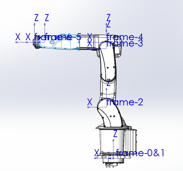
The following image shows the reference frames established for each axis based on the robot’s home pose, conforming to the SphericalWrist_SixAxis robot basic configuration. For more information on robot configuration, see SphericalWrist_SixAxis (common industrial six-axis spherical wrist robot).
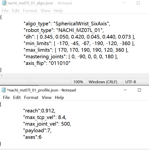
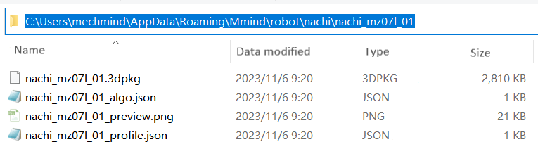
The algorithm (nachi_mz07l_01_algo.json), and configuration (nachi_mz07l_01_profile.json) parameters for the robot can be obtained from the robot manual, as shown in the image below.
Issue
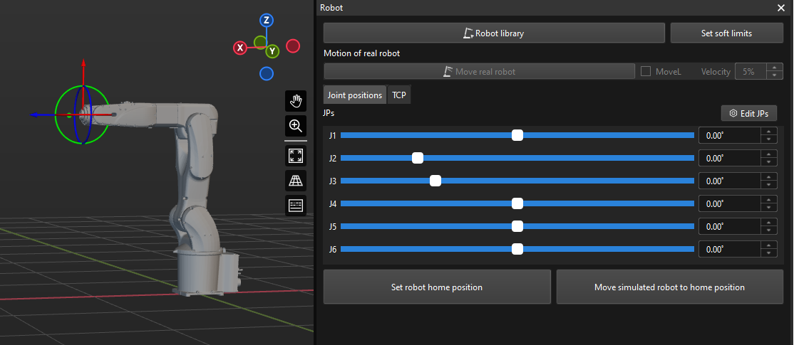
When importing the robot STL file and related parameter files into Mech-Viz (Robot Model Importing Manual), the robot model displayed in the Mech-Viz robot window shows a forward tilt of 90° in the J2 axis, as shown in the figure below, inconsistent with the actual robot’s initial home position.

Troubleshooting
Check poses at axis limits
Taking NACHI MZ07-01 robot (differing only in the J3 working envelope) from the same MZ series as a reference robot model, compare the motion range of the J2 axis between the two robots.
Adjust the J2 to the axis limits for both robots in Mech-Viz, and check if any collisions or interference occur between the joints in different orientations and poses. (If there is no reference robot model, you can also check the robot itself).
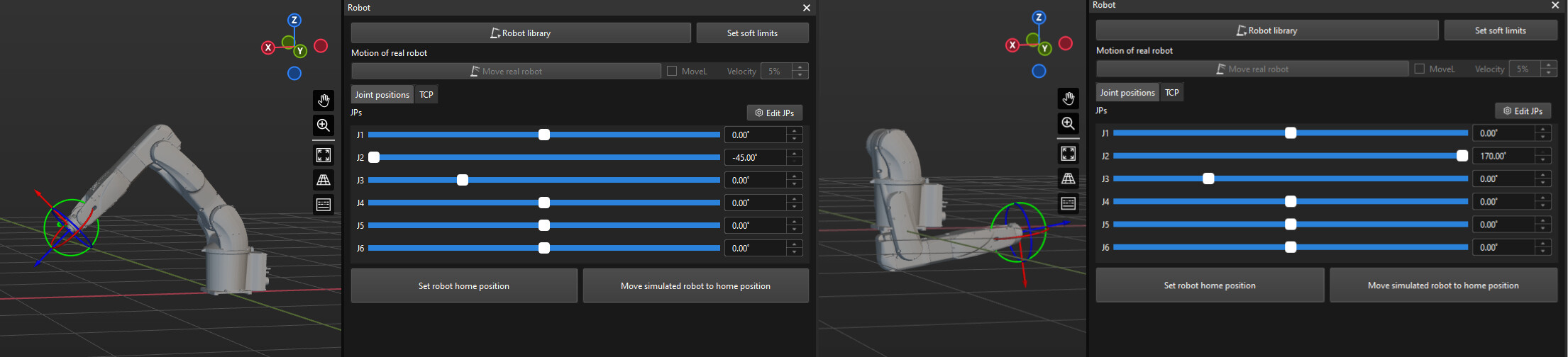
The MZ07L-01 robot at the minlimits and maxlimits of J2 is shown in the image below.
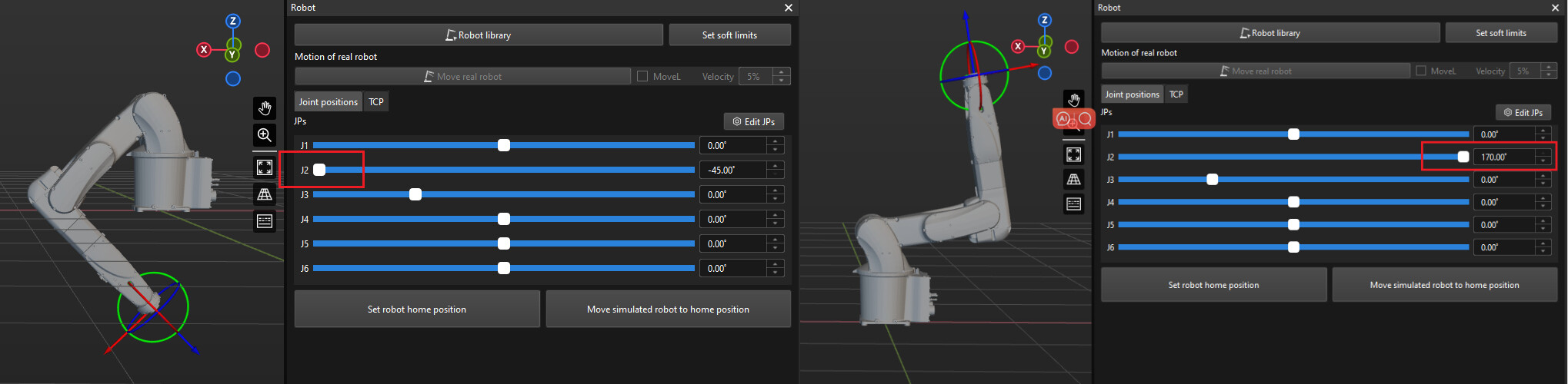
The MZ07-01 robot at the minlimits and maxlimits of J2 is shown in the image below.
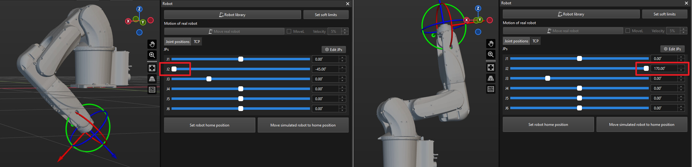
It is evident that the minlimits and maxlimits of J2 for the robot are consistent with the actual situation. This rules out basic factors such as rotation direction and axis limits.
Adjust the J2 axis (mastering_joints) parameters
The mastering_joints parameter in the [robot]_algo.json file defines the pose of the robot with the angle of each axis being 0°. We can modify the mastering_joints parameter to see if the inconsistency is caused by the incorrect pose of J2 axis with its angle being 0°. For more information on this parameter, see Pose of the Robot with the Angle of Each Axis Being 0°.
-
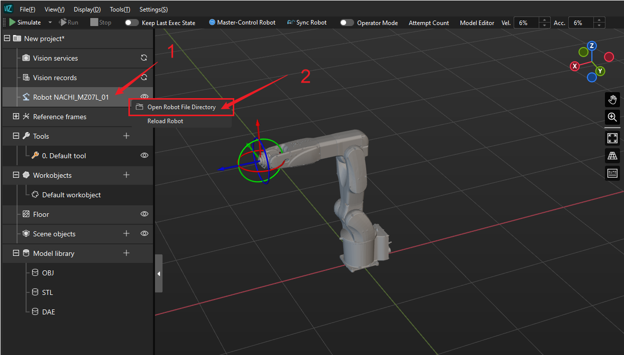
Locate Mech-Viz’s robot file directory of the MZ07L-01 robot.
In Mech-Viz software version 1.8.0 and above, you can directly open the robot file directory by right-clicking on the robot name in the Resources, as shown in the figure below.
-
Find the
nachi_mz07l_01_algo.jsonfile and open it with Notepad. -
Change the J2 value in the mastering_joints (J1, J2, J3, J4, J5, J6) parameters from -90 to 0, as shown in the image below.
-
Save the modified files and click on the “Reload Robots” option to ensure that the new configuration takes effect.
The robot’s initial pose should now be restored to the same pose as the actual robot, as shown in the image below.
-
Adjust the J2 to the axis limits again, and check if any collisions or interference occur between the joints.


It is evident that modifying the J2 value in the mastering_joints parameter may change the J2 pose at axis limits, and the J2 poses at axis limits are now inconsistent with the actual robot and there is interference between the robot body, as shown in the image above (incorrect J2 poses at axis limits).
This indicates that there are no issues with the J2 axis pose when its angle is 0°, and it is not the source of the inconsistency. Restore the mastering_joints parameters and proceed to the next troubleshooting step.
Adjust the J2 axis (home_jps) parameters
Next, investigate the default pose of the J2 axis for the robot. The home_jps parameter in the [robot]_profile.json.file defines the default pose of the robot model in the software. For more information on this parameter, see Initial Pose of Robot.
-
Find
nachi_mz07l_01_profile.jsonfile in the robot file directory and open it with Notepad. -
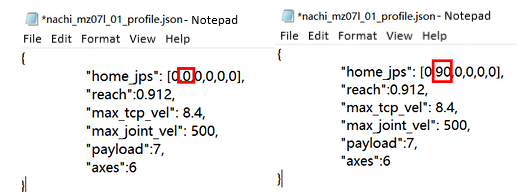
Based on a forward tilt of 90° in the J2 axis in the issue, change the J2 value in the home_jps (J1, J2, J3, J4, J5, J6) parameters from 0 to 90, as shown in the image below.
Note: If the home_jps parameter is not present in this file, manually add it.
-
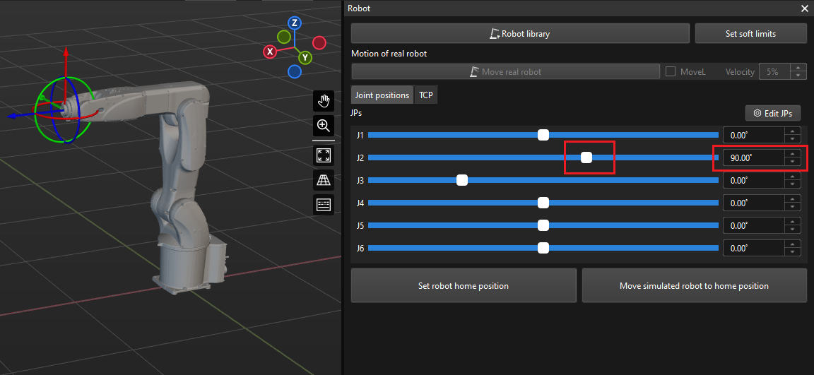
Check the robot’s initial pose, and at this point, the pose of J2 axis should be the same as the actual robot. Compare this with the robot’s pose in the Issue section, and you’ll notice changes in slider positions and angle values.
-
Check the pose of J2 at axis limits again, as shown in the image below, and there is no more interference.
It can be observed that the factor affecting the initial pose of this robot is an incorrect default pose. Ultimately, it is necessary to combine the robot’s actual pose and tool pose for verification to ensure the correctness of the robot model.
Through the adjustments outlined above, it becomes evident that the definitions and logic of the mastering_joints and home_jps parameters are entirely different. In certain situations, these two sets of parameters may combine to create new issues. Therefore, when troubleshooting problems, it is crucial to consider the impact of both sets of parameters.