1. What do Mech-Vision projects involve?
Mech-Vision projects mainly involve point cloud processing, pose transformation and adjustment, and logic judgment (error prevention). Any factors that impact these three steps can lead to low accuracy in Mech-Vision projects.
For example,
- The impact of lighting conditions, the material of the workpiece, and the reflective properties of surrounding objects on the stability of the workpiece’s point cloud.
- The impact of the ambient temperature on the camera hardware and its intrinsic and extrinsic parameters.
- Mech-Vision project configuration (with or without instance segmentation), matching methods, matching parameters, pick point configuration, etc.
- Unreasonable combination of logic judgment and error prevention, etc.
2. Pose repeatability verification of Mech-Vision projects
The stability of vision recognition can be checked by the repeatability of the pose output in the Mech-Vision projects.
2.1 Verification tool
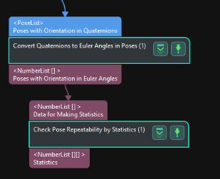
The repeatability of the poses in most vision projects can be evaluated using the Check Pose Repeatability by Statistics Step in Mech-Vision, as shown in the figure below.
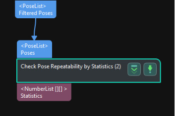
The camera will capture 10–20 images on the same workpiece at each position first, and this Step will calculate the statistics of the workpiece poses at each position, so as to evaluate whether the projects run stably according to the statistics.
For more information on this Step, see Check Pose Repeatability by Statistics.
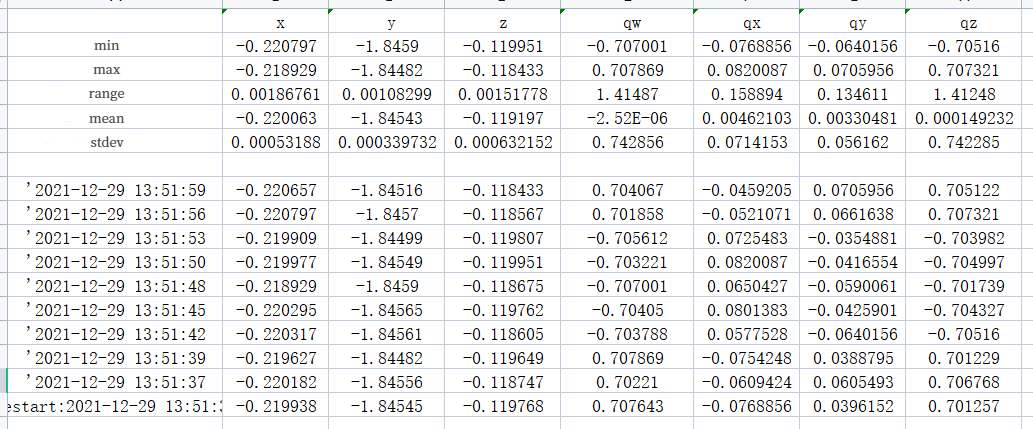
By default, the format of the output poses is X, Y, Z values of the poses and quaternions, as shown in the spreadsheet below.
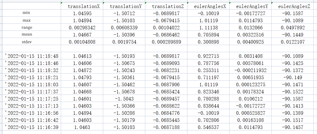
When Euler angle values are needed for the output, connect the Convert Quaternions to Euler Angles in Poses Step before the Check Pose Repeatability by Statistics Step. For more information on the Convert Quaternions to Euler Angles in Poses Step, see 2.4 Conversion tool.
2.2 Verification scheme
During on-site picking operations, especially in situations with relatively large picking areas or areas where picking performance is unstable, it’s necessary to check pose repeatability of individual workpieces at multiple positions, so as to evaluate the picking accuracy at different positions based on the output data.
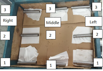
For a deep bin picking task, which is common for metal workpieces, try to partition the space of the bin as shown in the figure below. Determine appropriate positions for the single workpiece used for testing based on the positions of workpieces on site. During the placement, ensure the workpiece remains relatively stable and will not be easily displaced by minor external disturbances. Also, to avoid misrecognitions, make sure that there is only one single workpiece in the camera’s FOV.
Note: Before testing, make sure that the workpiece’s point cloud is relatively complete and meets the requirements of the on-site project. This is to eliminate cases where unstable picking may result from severely defective point clouds. If the cause cannot be determined, make relevant records.
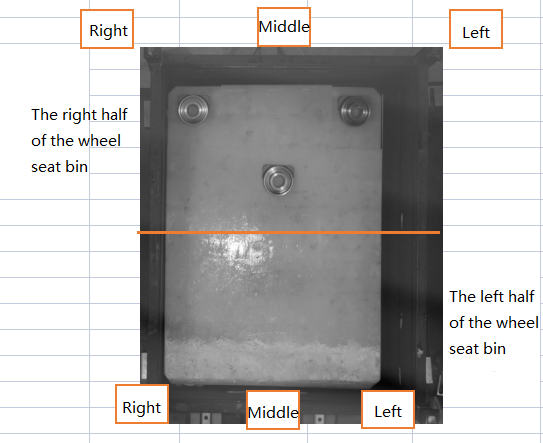
Capture images of a single workpiece 10 times at each position determined previously. The figure below shows different positions for image capture in the right, middle, and left areas of the bin.
The obtained data is shown in the spreadsheet below. The range in the data spreadsheet can be used to analyze the pose repeatability of the single workpiece at one position.

2.3 Use cases
The Check Pose Repeatability by Statistics Step can be used to verify whether the parameter settings in the 3D Matching Procedure or the matching methods are effective.
The usage scenarios are as follows:
- When separately tuning each parameter in the 3D matching Procedure, use this Step to check the effectiveness of the vision project parameter tuning.
- For the 3D Coarse Matching Step, use this Step to compare the influence of Surface Matching Easy Mode and Surface Matching on the 3D matching outputs.
- Compare the accuracy of Edge Matching and STL Model Matching.
The following shows a comparison of the repeatability effects between Edge Matching and STL Model Matching for wheel seats:
-
Edge Matching:
Use Check Pose Repeatability by Statistics Step to capture images of a single workpiece at the same position 10 times, and obtain the data for comparison.
The following spreadsheet shows the obtained data:
- The range of X-axis coordinates is 0.38mm;
- The range of Y-axis coordinates is 0.46mm;
- The range of Z-axis coordinates is 0.28mm.
The repeatability of the current matching outputs can meet the needs of on-site projects.
-
STL Model Matching:
Same to Edge Matching, images of a single workpiece are captured at the same position 10 times to obtain data for comparison.
The following spreadsheet shows the obtained data:
- The range of X-axis coordinates is 1.70mm;
- The range of Y-axis coordinates is 1.30mm;
- The range of Z-axis coordinates is 3.51mm.
It can be seen that the accuracy of STL Model Matching is relatively low. Although the impact of parameter setting cannot be ruled out, the Check Pose Repeatability by Statistics Step can effectively verify the stability of a project based on the pose data.


Pros and cons of Edge Matching and STL Model Matching are concluded in the table below:
| Matching Method | Pros | Cons |
|---|---|---|
| Edge Matching | 1. Short matching time 2. High matching accuracy |
1. High dependence on the point cloud stability of workpiece features 2. Limited application scenarios |
| STL Model Matching | Broad application scenarios | 1. High quality requirements on the workpiece point cloud 2. Long matching time 3. High difficulty of parameter adjustment when high accuracy is needed, and low matching accuracy. |
At the project site, the collected pose data of the workpieces can be imported to project simulation. Before the Procedure Out Step, connect the Check Pose Repeatability by Statistics Step to verify the parameter settings of the projects and to verify the stability of positioning and recognition under different parameter settings.
2.4 Conversion tool
When the Euler angle values are needed for the output, connect the Convert Quaternions to Euler Angles in Poses Step before the Check Pose Repeatability by Statistics Step, as shown in the figure below.
For more information on the Convert Quaternions to Euler Angles in Poses Step, see Convert Quaternions to Euler Angles in Poses.
The following figures show the adjustable parameters for this Step in Mech-Vision.
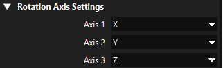
Rotation Axis Settings: The order of the rotation axis can be customized.
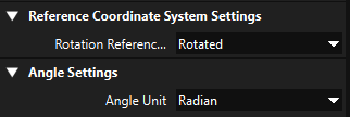
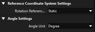
Reference Coordinate System Settings: Choose the rotation reference coordinate system.
Rotated: The axis of the pose is used as the rotation axis.
Static: The axis of the world coordinate system is used as the rotation axis.
Angle Settings: Choose the unit of angles.
Radiant: The unit of angles is radiant.
Degree: The unit of angles is degree.
When the two steps are connected sequentially, the format of the output poses is X, Y, Z values of the poses and X, Y, Z values of Euler angles, as shown in the spreadsheet below.