Introduction
In Mech-Viz, the initial poses of each axis of the robot are consistent with the actual robot. However, when teaching the robot to rotate a certain angle, and synchronizing the rotation to the robot model in Mech-Viz, there is a significant difference in their poses.
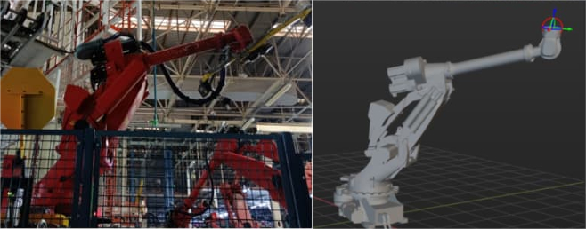
This passage takes the COMAU_NJ370_3 robot as an example. As shown in the diagram below, when the joint positions for the robots are the same, the real robot flange is facing diagonally down to the right, while in Mech-Viz, the robot flange is facing diagonally up to the right. There seems to be a certain symmetrical relationship between the orientations.
Note: When multiple joint poses are inconsistent, it is not easy to observe the symmetrical relationship in the combined pose. In this case, each joint should be checked one by one in the order of J1, J2, J3, J4, J5, J6. If there is a symmetrical relationship in the rotation direction of a certain joint, proceed directly to the Solution part.
From the comparison of values in the TCP, almost all values are inconsistent. Analyzing the statistical results of data from other cases, it was found that this is somehow related to the number of reverse joints. However, it is mostly manifested as a small difference in the value of a certain coordinate between the robot in Mech-Viz and the actual robot, as shown in the table below:
| X | Y | Z | RX | RY | RZ | |
|---|---|---|---|---|---|---|
| TCP of the robot in Mech-Viz | a | b | c | d | e | f |
| TCP of the real robot | a+g | b+h | c+i | k | m | n |
Here, the joint positions of the real robot are (144.960000, 36.000000, -76.910000, 170.900000, -72.250000, -83.340000). You can quickly set the robot to the specified pose in Mech-Viz by pasting these values into the JPs editing boxes, as shown in the figure below. This also facilitates the repeated adjustment and comparison of subsequent parameters.

Troubleshooting
We can try adjusting the joint positions of the robot in Mech-Viz to fit the real robot pose. By checking each joint position in the order of J1, J2, J3, J4, J5, and J6, we found that the poses of J1, J2, J3, and J4 axes are consistent, but only the orientation of the J5 axis is not corresponding. Drag the joint position of J5 to around 72.25°, the robot model’s pose is as shown in the figure below,

Now comparing the poses between the two robots, we found they match with each other, and the rotation direction of J5 in Mech-Viz turns out to be opposite to the real robot.
Note: Engineers on-site can jog each joint of the robot one by one to check the real rotation directions of the joints, so as to correct the rotation parameters.
Solution
-
Right-click the robot name to open Robot File Directory and find the
[robot]_also.jsonfile. Open it with Notepad.
-
Change the axis_flip (J1, J2, J3, J4, J5, J6) parameter for J5 from 1 to 0.
-
Reload the robot and input joint positions for the robot again. The comparison results are shown in the figure below. It can be seen that the pose of the robot in Mech-Viz at this time is consistent with the real robot (with slight differences due to the precision errors related to the robot configuration). In addition, another set of robot joint positions can be used to retest the accuracy of the robot model."


