My camera is fixed on a bracket. And I have an AMR with poor positioning accuracy. So I want to use markers after each positioning to perform dynamic extrinsic parameter calibration. How can I do that?
Solution:
Overview

In the figure above, there are four parts:
- Green: the AMR
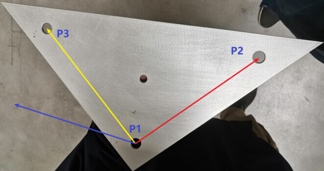
- Yellow: the solid marker (or calibration board) for extrinsic paratmeter calibration
- Red: the bin and workpieces
- Blue: camera on bracket
-
Fix a calibration board or a solid marker (e.g., 3 spheres, 3 holes) on the AMR and obtain its pose in the robot’s coordinate system using the robot teach pendant, denoted as P2-1
-
Move the AMR into the camera’s field of view, and using point clouds from camera 3, calculate the pose of 2 in the reference of 3, denoted as P2-3;
-
Calculate the pose of camera 3 in the reference of robot arm 1, i.e., the extrinsic parameters ETH (P3-1), using poses P2-1 and P2-3;
-
Based on the new extrinsic parameters, capture images and calculate the poses of the workpieces in the robot’s coordinate system
Projects
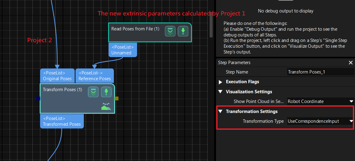
- Set up two projects, Project 1 and Project 2. Project 1 calculates the new ETH extrinsic parameters (P3-1). Project 2 uses the new extrinsic parameters to calculate the pose of workpieces in the robot’s coordinate system.
- In Project 2, for Step “Transform Poses”, select “Use Correspondence Input” as the transformation type, and use the results saved in Project 1 as the reference pose.
Important Notes:
The key to ensuring accuracy in this solution includes:
- Ensuring the stability of the AMR before image capturing.
- Avoiding chassis movement during robot actions.
- Using relatively large markers when possible.
- Precise calibration of the robot’s TCP (Tool Center Point).
- Ensuring good repeatability in the marker recognition project.
- If using collaborative arms, minimizing significant changes in the robot arm’s motion and aiming for consistent picking poses.