Background
-
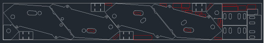
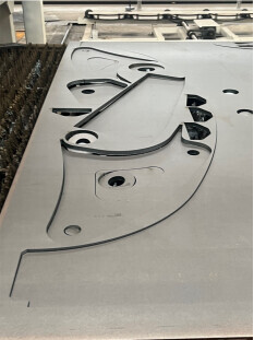
Steel plate sorting refers to the entire process of first cutting the formed steel plate according to the nesting layout and then, based on a certain rule, sorting and stacking small steel plates, as shown in the figure below):
- Steel plate stacking, etc.
- Steel plate sorting
- Steel plate cutting
- Steel plate surface marking
- Steel plate loading.
-
Typically, the size of the formed steel plate is generally 2500x10000mm, with a thickness of 3-70mm. The formed steel plate is cut into small plates with defined shapes according to the nesting layout using laser or plasma equipment.
-
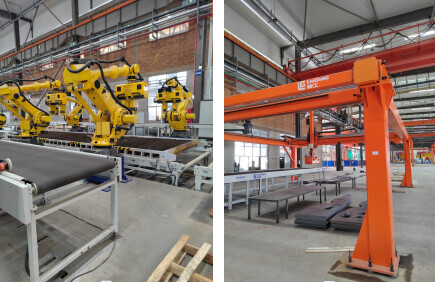
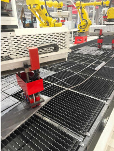
To achieve automatic sorting and stacking of steel plates, the cut steel plates are usually classified by size, and different devices are used for sorting and stacking different-sized steel plates. Small steel plates (L<1000; W<800; T<1T) are generally sorted and stacked using a combination of industrial robots and end effectors, while medium-sized steel plates (1000≤L<2000; 800≤W<1200; 1T≤T<2T) and large-sized steel plates (2000≤L<4000; 800≤W<1200; 2T≤T<3T) are generally sorted and stacked using a combination of gantry manipulators and end effectors. Other sizes (miniature and oversized) are handled manually or by lifting equipment.

Basic structure introduction
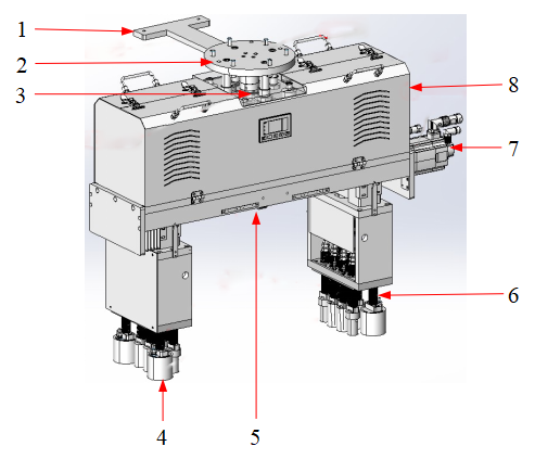
The basic structure of the large end effector for steel plate is similar to that of the small end effector (with or without a spacing between the servo device and the magnetic column).
- Vision Bracket: Used to mount a vision camera (EIH).
- Connecting Flange: Used for the installation and connection between the end effector and robots, gantry manipulators, and other executing mechanisms.
- Torque Sensor: Monitors the load status of the end effector to prevent overload.
- Magnetic Column: Key component for adsorbing and releasing steel plates.
- Main Frame: Installation of non-standard processed parts and components; bearing structural components, and the weight of steel plates.
- Spring Buffer Mechanism: Provides the electromagnetic with a telescopic buffering function, beneficial for contact adsorption, and prevents overload of the end effector or executing mechanism.
- Servo Screw Mechanism: Controls the adjustment of the spacing between the electromagnetic columns on the left and right sides, adapting to different sizes of steel plates.
- Cover Shell: Protects electrical components integrated on the end effector (PS: Electrical components can be installed outside the end effector depending on the situation, usually on the ground or on the robot’s three axes).
Design of steel plate end effector structure
Magnetic column (electromagnetic group) design
Material selection
-
The magnetic column material is generally recommended to be an electromagnetic magnet. The principle of the electromagnetic magnet is to control and convert the distribution of its internal magnetic circuit through the control and transformation of different characteristics of different permanent magnet materials. It balances the permanent magnetic field within the system, representing demagnetization (relaxed state) and magnetization (clamping state) externally.
Features of the electromagnetic magnet:
- No power is used in the adsorption state, and there is no thermal deformation of the workpiece due to heating.
- There is no risk of dropping the workpiece due to power failure during gripping, ensuring high safety.
- Energy-saving, excellent magnetic force effect.
-
After the end effector works for a certain period, the surface of the magnet will adsorb some iron scraps, affecting the magnetic adsorption. Solution: Regularly clean the surface of the magnet, and clean the iron scraps after cutting the steel plate.
Magnet numbering
- Based on the rules and requirements of the sorting software, the internal magnet numbering should be unified, and the numbering of internal IO points should correspond one-to-one with the magnet numbering. As shown in the figure below. In addition, two end effectors are symmetrically installed, and the magnet numbering rule should be consistent.

Reasonable distribution
- Steel plate sizes vary, and one end effector often needs to adapt to multiple steel plates. Therefore, it is necessary to reasonably allocate the quantity and layout of electromagnetic magnets according to the nesting diagram, and different specifications of electromagnetic magnets can be used for layout if necessary.

Relevant sensors for end effector
Torque sensors
-
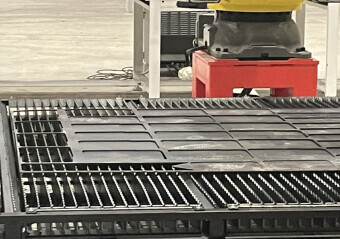
Formed steel plates cut by laser or plasma will appear in various states.
-
Small steel plates may fall into the waste bin, as shown below:
-
Small steel plates may be tilted, as shown below:
-
During the end effector picking process, issues such as the steel plate sticking or adhering to the waste bin may occur, as shown below:
-
-
These issues will increase the additional load when the end effector picks up the target steel plate, and the electromagnetic or other executing devices may be damaged due to overload. Therefore, installing a torque sensor between the connecting flange and the main structure can monitor the load status of the end effector in real time, avoiding damage caused by overload when the end effector adsorbs steel plates.
Omission detection sensors
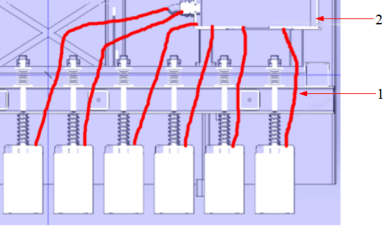
- The technical difficulty of detecting whether the workpiece is present lies in the variety of workpiece types and varying sizes, which requires that the detection sensors must be installed at a reasonable position; otherwise, workpiece omissions may occur.
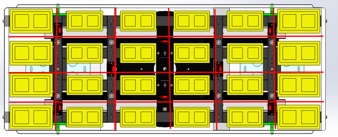
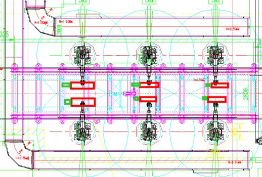
- Since the magnets are arrayed, the magnets near the center of the magnetic field have the highest probability of attracting steel plates. Simultaneously, multiple sensors need to be arranged in the central area to prevent workpiece omissions. As shown by the red line in the figure below, utilize the spacing between the electromagnetic magnets to place the sensors.
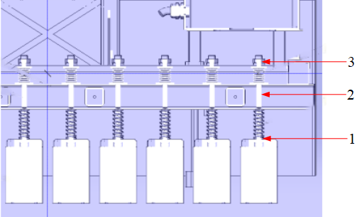
In-Place sensors
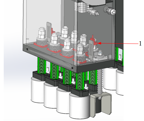
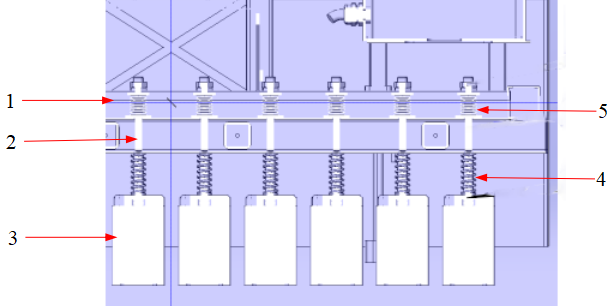
- To prevent damage to the end effector caused by exceeding the allowed compression of the buffering mechanism, it is necessary to install an in-place sensor on the buffering mechanism. This sensor must immediately stop the downward pressure once it detects the in-place signal.
1: In-place sensor.
Small end effector design
Structure and overall size of small end effector
-
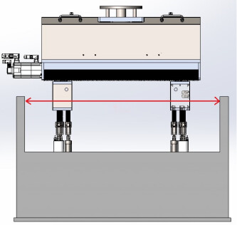
When the small end effector is palletizing in deep bins, particular attention must be paid to the collision between the end effector and the material bin. A certain depth margin must be reserved to avoid collisions between the edges of the material bin and the main body of the end effector.
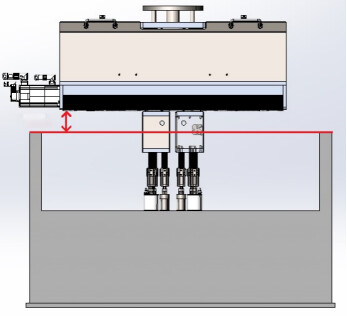
-
The maximum working width of the end effector must be smaller than the spacing between the edges of the material box. To meet the usage requirements, it is preferable to have a smaller overall size and weight for the end effector. It is recommended that the majority of the main frame structure, while meeting the load-bearing requirements, can be constructed using aerospace aluminum material to reduce the overall weight of the end effector.
Relationship between small end effector and 3D camera position
- Multiple robots are collectively located at the steel plate sorting station, and the fixture zero point position should consider the requirements of the analysis software.
Large end effector design
- When the end effector picks up a steel plate, it presses down on the steel plate. The middle part of some steel plates is hollow, and the magnets at both ends start to move upward due to pressure. At this time, the middle of the load-bearing beam bears downward pressure, while both ends bear upward pressure, easily causing the middle of the load-bearing beam to sag lower than the ends. At this point, the spring force and the selection and calculation of the compression stroke of the magnetic field become crucial. The sum of the compression forces of all springs involved must be less than the force causing the deformation of the beam. At the same time, there must be a margin of compression to avoid the direct impact of the downward force of the executing mechanism on the beam.
- Steel plate
- Load-bearing beam
- Hollow part of the steel plate
- Upper spring
- Lower spring.

Electromagnetic buffer structure design
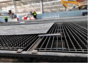
- After the steel plate is cut, it undergoes thermal deformation and becomes uneven, as shown below. Sometimes, the deformation amount is significant, so a spring buffer mechanism needs to be installed for each electromagnetic magnet.
Smoothness
-
Self-lubricating copper bushings or linear bearings: If the up and down movement of the magnet guide column is not smooth, it can easily lead to the occurrence of situations such as the electromagnetic magnet not resetting and the guide rod bending. Therefore, the guide column should use self-lubricating copper bushings or linear bearings, as well as other reliable guidance measures, to avoid sticking and unsmooth movement between the guide rod and the guide bushing.
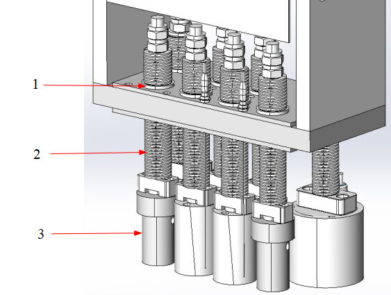
- Frame
- Guide rod
- Magnetic column
- Upper spring
- Lower spring.
-
The relative position of the bushing to the magnetic column has a certain impact on the overall smoothness. As shown in the figure below, the guide rod moves relative to the bushing. The guide rod has the longest lever arm when it is not retracted. At this time, the contact surface with the bushing bears the largest torque. After long-term use, the guide rod is always subjected to torsional deformation, and the sliding resistance increases, making it easy to get stuck.
- Oil-free bushing
- Guide rod & spring
- Electromagnetic magnet.
-
Try reversing the sliding structure. Place the bushing closer to the electromagnetic magnet, so the bushing slide moves relative to the guide rod, which shortens the lever arm, reduces the torque, and extends the service life of the guide rod or even solves the problem of guide rod deformation. As shown in Figure
- Guide rod spring
- Oil-free bushing
- Sliding structure.

Firmness of fasteners
- The magnets and accessories in the end effector are movable parts, and screws, nuts, etc., should consider using thread glue or other anti-loosening devices. Periodically check the looseness of fasteners, and the mechanism design should add functions to prevent the guide rod and magnets from falling.
- Magnet connection block |
- Guide bushing fixation |
- Top nut of the guide rod.
Convenience of replacement for individual permanent magnets and buffer mechanisms
- In the process of using the end effector, it is necessary to consider the convenience of maintenance and repair. While the electromagnetic, springs, and guide rod mechanisms are mechanically connected, there is also a multi-core wire connected to the electrical control box. To facilitate the replacement of magnets, the design phase needs to consider the operational space for personnel and tools, improving the convenience of replacement.
- Electrical box
- Multi-core wire.
Electrical components installation
Small end effector
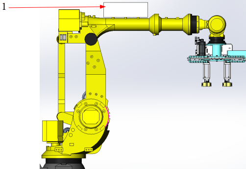
- The small end effector is generally installed at the end of the robot. Considering the arm span and load of the robot, the overall size of the end effector should not be too large, and the weight needs to be well controlled. At this time, if the robot’s arm span and load are sufficient, and considering the convenience of maintenance for magnets, guide rods, and electrical components, the electrical components and the end effector body can be integrated, as shown in the figure. The red box contains electrical components.
Large end effector
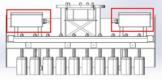
- If the robot’s load capacity is insufficient, the electrical components can be separated from the end effector. The electrical components can be additionally accommodated in a separate electrical box placed on the robot’s third axis or outside the robot’s body, as shown in the diagram. In this configuration, the dimensions and ease of maintenance of the end effector’s mechanical body are easily controllable. However, there is an increase in the cabling between the electrical box and the end effector, usually requiring cable conduits, which may pose a certain risk of cable replacement. This situation can be addressed by using multi-core cables to mitigate the subsequent cabling risks.
- Electrical box.
- Electrical box.
Gantry
-
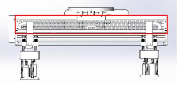
If the height and stroke of the Gantry’s Z-axis are sufficient (with an increased Z-axis travel), with the convenience of maintenance for magnets, guide rods, and electrical components being considered, the electrical and mechanical components can be integrated, as shown in the diagram. The red box contains electrical components.
-
If the electrical box is installed outside the end effector, the size of the end effector becomes smaller, and mechanical maintenance convenience increases. However, there are more connections between the electrical box and the end effector, so when troubleshooting, multiple service personnel may be needed for assistance or to reach higher areas. Based on practical project experience, if the electrical box is separated, it is generally placed on the beam of the frame’s Y-axis (the electrical box only follows the movement of the X-axis).
