1 Explanation of “Interference in the Baseline Direction”
-
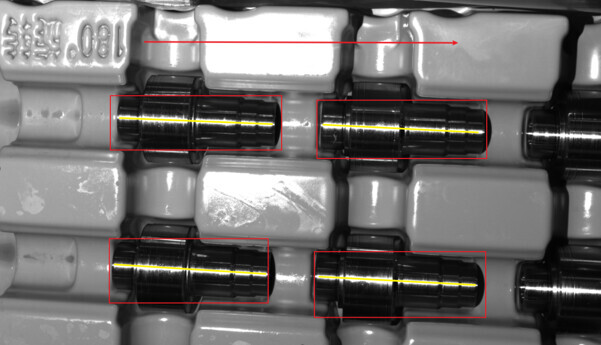
Camera Baseline and Highlight Line
Regarding the diagram below, you can see that the camera baseline direction is parallel to the long axis of the rod.
(The direction of the arrows in the image represents the camera baseline direction, and the yellow line indicates the highlight line.)

-
Causes of the Highlight Line on the Rod in the Image (Emphasized by the Yellow Line):
-
Material Properties of the Object Itself
The overall shape appears as an arc, with the highlighted reflection material, such as the smooth rod shown in the image. -
Structured Light from the Camera & Ambient Light
The influence comes from the surrounding lighting or from the fact that the camera directly projects onto the surface of a bright object. -
Multi-Path Reflections from Surrounding Interference
There are interfering objects around the captured object, causing the interfering light source to be projected onto the workpiece again, forming the “highlight line,” which is the result of multiple reflections.
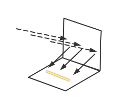
In the image:
- Vertical plane: The interfering surface.
- Dotted line: Interfering light rays.
- Yellow line: Highlight line.
2 Relationship between Highlight Line and Baseline Interference
Current Known Theories
1) When the “highlight line” brightness is relatively uniform and it is roughly parallel to the baseline, there is no interference in the baseline direction.
2) When the “highlight line” is perpendicular to the camera baseline, it causes baseline interference issues.
Therefore, to avoid point cloud fluctuations caused by interference, it is best for the “highlight line” to be parallel to the baseline, minimizing the impact.
3 Real-life Case
Problem
Significant fluctuations can be observed at the edge of the hole position.
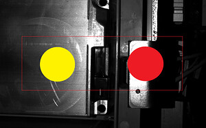
Left: On-site photo
Right: Point cloud image
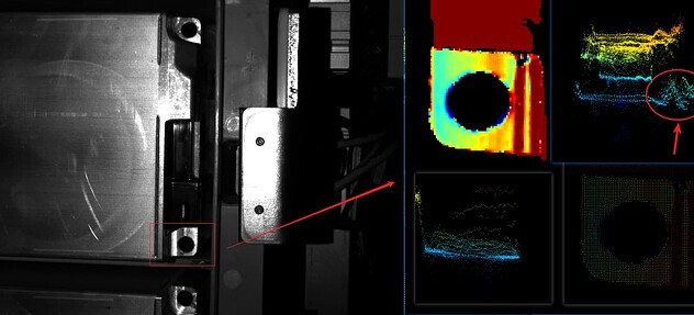
Analysis
Left: On-site photo
Right: 2D Flash image
Camera Baseline Direction
Analysis
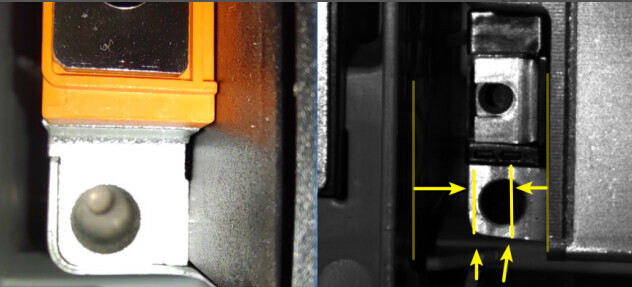
- The hole is in a concave position, and interference is easily formed from the sidewalls.
- Multiple reflections lead to the formation of a relatively fixed bright line, as shown by the yellow arrow line in the image, which is the highlight line. The formation of the highlight line corresponds to the third method mentioned above, of which the problem is caused by multi-path reflections of surrounding interfering objects.
- It can be observed that the camera baseline direction (red arrow) and the “highlight line” are in a perpendicular position. According to existing theories, this configuration causes baseline interference issues, leading to point cloud fluctuations.
According to existing theories, when the “highlight line” is perpendicular to the camera baseline, baseline interference issues occur, resulting in point cloud fluctuations.
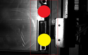
Problem Resolution
To address the baseline interference problem, the optimal approach is to change the camera baseline direction, ensuring that the baseline and the highlight line are parallel. In the current case, rotating the camera by 90° achieves this goal.
The actual adjustment is shown in the following image
In the image, the yellow circle represents the light source, and the red circle represents the camera.