1. Common Methods to Reduce Vibration in Equipment Placement and Installation
1.1 Insufficient Strength or Stiffness of Equipment Placement Surfaces
-
Symptom:
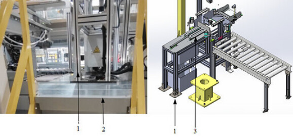
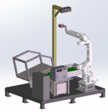
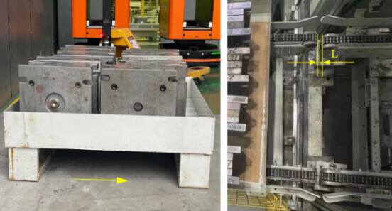
- The aluminum frame is placed on a steel platform. When the material pusher mechanism on the aluminum frame is in operation, the barcode scanner will shake noticeably, thus affecting the success rate of code reading. (As shown in the pictures: 1. aluminum frame 2. steel platform 3. material pusher mechanism)
- The aluminum frame is placed on a steel platform. When the material pusher mechanism on the aluminum frame is in operation, the barcode scanner will shake noticeably, thus affecting the success rate of code reading. (As shown in the pictures: 1. aluminum frame 2. steel platform 3. material pusher mechanism)
-
Solution:
- The stiffness of the steel platform on-site is insufficient, with a thickness of only 3 mm. Additionally, there is no steel beam support beneath the aluminum frame.
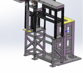
It is recommended to add a welded steel frame beneath the steel platform so that the aluminum frame can be directly installed on the steel frame. In cases of limited space, the welded steel frame may need to be assembled in several parts beneath the steel platform.
- The stiffness of the steel platform on-site is insufficient, with a thickness of only 3 mm. Additionally, there is no steel beam support beneath the aluminum frame.
-
Additional Information:
-
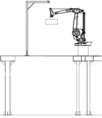
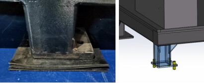
The camera mounting frame is placed on a manually constructed welding platform (as shown below). During robot operation, the camera mounting frame will shake severely.
-
Due to the limited thickness of the floor, the depth of holes for expansion bolts or chemical bolts may be insufficient during the installation of the camera mounting frame. This can result in minor disturbances during production, leading to significant shaking of the camera mounting frame.
In practice, support structures can be added beneath the camera mounting frame. The camera can also be mounted on the side wall or ceiling.
-
1.2 The Floor’s Flatness Does Not Meet the Required Standard.
-
Symptom:
- The robot, camera mounting frame, and related equipment are all installed on the same floor. If the floor’s flatness does not meet the standard, the camera mounting frame and grippers will experience severe shaking during high-speed robot movements.
- The robot, camera mounting frame, and related equipment are all installed on the same floor. If the floor’s flatness does not meet the standard, the camera mounting frame and grippers will experience severe shaking during high-speed robot movements.
-
Solution:
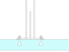
- Level the surface of the floor and secure the entire unit using foundation bolts.
- Place shims under the unit’s legs (as shown in the left picture). It’s not recommended to adjust the height of each leg by adding leveling screws one by one (as shown in the right picture).
2. Solutions to Reduce Vibration in Product Flow Process
-
Symptom:
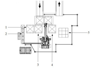
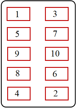
- The top-down view below shows the layout of a storage and retrieval robot cell. During operations, palletizing and depalletizing are performed between stations 1, 3, 4 and stations 2, 5. Specifically, in storage operations, the robot places products from station 2 or 5 onto station 1, 3, or 4 according to predefined pallet patterns, following commands from the host computer. In retrieval operations, the process is reversed.
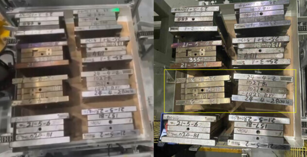
The end products are molds. During production, multiple pallets are retrieved in each operation, and the robot picks only 1-2 molds per pallet. During storage operations, the host computer controls the robot to continue palletizing dynamically according to the quantity requirements of molds per pallet. Consequently, once a pallet is filled, the products may undergo multiple operations of storage and retrieval without being picked up by the robot. As shown in the picture below, the left side illustrates the situation after the initial palletizing, with molds neatly piled on the pallet, which meets the requirements. The right side shows that after multiple retrievals, the molds within the yellow frame line are positioned closely due to vibrations, which causes scratches during picking. Interference from grippers and adjacent large molds may prevent successful picking of smaller-sized molds.
- The top-down view below shows the layout of a storage and retrieval robot cell. During operations, palletizing and depalletizing are performed between stations 1, 3, 4 and stations 2, 5. Specifically, in storage operations, the robot places products from station 2 or 5 onto station 1, 3, or 4 according to predefined pallet patterns, following commands from the host computer. In retrieval operations, the process is reversed.
-
Solution:
-
It’s found that the conveyor line motor was not equipped with a frequency converter. Therefore, abrupt motor stops or emergency accelerations in operation could scatter the products on the pallet. After installation of the frequency converter and the subsequent adjustment, the stability of piled products improved after multiple operations of storage and retrieval.
-
Additionally, the bottom structure of the pallet is shown on the left side below. The yellow arrows indicate the actual movement direction of the pallet on the conveyor line. When the pallet passes through the connection between two successive conveyor lines, the large gap between these lines causes significant pallet vibrations. Thus, for future projects with similar scenarios, it is recommended to mount the pallet support legs along the direction that the conveyor line moves (rather than the perpendicular direction shown in the picture) and minimize the gap between two successive sections of conveyor line.
-
When palletizing, it’s recommended to consider the pallet’s center of gravity in determining the stacking sequence, especially in cases where the entire layer cannot be fully loaded. This ensures pallet stability during operations.
-
3. Common Solutions to Reduce Vibration in Robot End Gripper
-
Symptom:
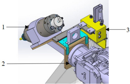
- At the robot end, a camera and devices causing vibrations (such as the grinder and screwdriver) are installed, as shown in the figure below. When the grinder or screwdriver is in operation, vibrations may decrease accuracy of the 3D camera and even damage internal components of the camera. 1. grinder 2. robot flange 3. camera
- At the robot end, a camera and devices causing vibrations (such as the grinder and screwdriver) are installed, as shown in the figure below. When the grinder or screwdriver is in operation, vibrations may decrease accuracy of the 3D camera and even damage internal components of the camera. 1. grinder 2. robot flange 3. camera
-
Solution:
- To avoid direct connections between the camera and the devices causing vibrations, it is recommended to install them separately at the robot end, which can effectively reduce the impact of vibrations. Install the device causing vibrations in the outer ring threaded hole 1 of the flange and the camera in the inner ring threaded hole 2.
- This is helpful.
- This does not solve my issue.